So I have decided to do a mini build thread. I figured I’ll try and point to some of the unique experiences during the build. And also be able to get more accurate suggestions to issues that arise. I am doing this after the fact. I have already completed the build for the most part. I received the printer a few days ago and did my first print last night.
Here is the how it went…..
First 3D Printer Build
What's in the Box
The pealing of the coating was not too bad. I had a help to so it went pretty fast.
- Quality time with the wife!
- Attachments
-
-
Bad Bearing
Got the base half way built and decided it was a good time to install the motors and bearings.
So looks like I am one of the first to get a new plastic bearing spacer. Not sure how I feel about them. I wonder what motivated the change, cost savings or functionality??
Either way I had issues with on of the bearings. After installing all of the bearings I was testing the smoothness of them and I noticed one was binding. After removing the discrepant bearing I found this.
It is somewhat difficult to see but there is a dent in the side of the bearing which was causing it to bind. I do not know if it shipped that way or it occurred during installation. If it’s and installation issue then it must be due to the plastic spacers is my guess. Either way I have order some extra bearing from SMC.
Last edited by aerouta on Sat Mar 30, 2013 1:28 pm, edited 1 time in total.
Re: First 3D Printer Build
I now have the basic frame completed. The assembly of the base was no too bad. It ended up relatively flat… I think. I did have to lightly sand one or two spots. I took my time tightening down the bottom and build plates. I would work on the inner most set of screws on the bottom and then do the same on the built plate. Then move to the next set of concentric screws on the bottom then then again on the top. I repeated this till all the screws were done.
I also used the tie down method for pulling the rails against the build plate and the top plates. I wish I got a picture.
I also used the tie down method for pulling the rails against the build plate and the top plates. I wish I got a picture.
- Attachments
-
Power Supply
I decided to start working on the power supply. I used a power supply for a computer that I had.
http://www.amazon.com/gp/product/B005FE ... UTF8&psc=1
I didn’t not want to take the chance of having the heat bed be under powered. I did stay with the 12v and did not step up to the 24v like some have.
I saw a build thread on this and I thought it looked like a good idea. I took apart the power supply and went to work stripping all the wires and recombining them. I have never stripped so many wires in my life.
I ran 12 guage lines out of the power supply to the Rambo. I originally had intended to use 10 guage but the connectors on the board didn’t like that. It would have been an overkill anyway. I used flex line so the routing was not difficult.
I also ran some extra ground and power lines to the compartment in case I want to add some extras. I have 3.3v and 5v available.
I also mounted the board inside the compartment and not on the door. I think this is a good spot. Thanks to however showed this on one of the 200 threads I have read..
http://www.amazon.com/gp/product/B005FE ... UTF8&psc=1
I didn’t not want to take the chance of having the heat bed be under powered. I did stay with the 12v and did not step up to the 24v like some have.
I saw a build thread on this and I thought it looked like a good idea. I took apart the power supply and went to work stripping all the wires and recombining them. I have never stripped so many wires in my life.
I also ran some extra ground and power lines to the compartment in case I want to add some extras. I have 3.3v and 5v available.
Cheapskate
This were not fun.. a lot of sanding and checking. I had thought I would use a dremel for this but after using it on the first one I decided against it on the the rest.
I tried to be really careful during the sanding process. I didnt not want to over sand these. But what happens if you end up with more play then you wanted? Is there a way to build out that surface or do you have to order replacement parts?
I tried to be really careful during the sanding process. I didnt not want to over sand these. But what happens if you end up with more play then you wanted? Is there a way to build out that surface or do you have to order replacement parts?
- Attachments
-
-
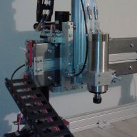
Extruder
This was one of my least favorite parts of the build. I cannot ever remember why I just know that looking at these pictures again makes me shudder. I know I did take it apart and reassemble several times. But my biggest issue was the set of bolts that was provided. One seemed to long and the other seemed to have been sitting at the bottom of the ocean. Anyway this part earned a trip to the hardware store to replace those items.
- Attachments
-
-
-
Cheapskate Bearings
I don’t have much pictures here of the build but I do want to point out two things that were minor issues.
First was the cheapskate bearings assembly. I noticed after placing them on the rails that the bearing sleeves were fouling against the axle supports.
After some trouble shooting I finally noticed that this was due to the orientation of the eccentric cams. So there are two possible orientations of the eccentric cams that will give you your desired spacing. (except for the maximum and minimum spacing). It turns out one of the two spacing solutions creates a fouling condition with the axle supports. If you land on this orientation keep looking. This would be good to include in the manual.
First was the cheapskate bearings assembly. I noticed after placing them on the rails that the bearing sleeves were fouling against the axle supports.
Rails
The next issue was the rails....
After fixing to fouling condition and getting the pressure just on against to rail to remove backlash and what not I noticed something else. At around midway up the rails the cheapskate felt like it was going over a bump. So I started trouble shooting again and found this.
It was difficult to get the shot with my iPhone camera. There was a scratch on the rails?!?! How? So I thought, “I should check the other rails too”. And sure enough, ALL my rails had at least two scratches each, all around the same points on the rail. What are the odds of having scratches on the single point were the bearing sleeves touch the rails?? I’ll take scratches on the side, the top, the inside, but not right where the bearing touch!! Just my luck.
The marks were light enough so I sanded it down with really fine sand paper. I hope this turns out ok.
After fixing to fouling condition and getting the pressure just on against to rail to remove backlash and what not I noticed something else. At around midway up the rails the cheapskate felt like it was going over a bump. So I started trouble shooting again and found this.
The marks were light enough so I sanded it down with really fine sand paper. I hope this turns out ok.
Soldering Heat Bed
Not much here. I ran out of my flex 12 gauge wire so had to switch to stranded wire. A lot more flexible than solid core but not as nice as the flex.
End Stop Switch
Not all of room up here. I had to be pretty careful here but I got them all in.
So running the wire....
I know someone as already commented on the build order provided in the manual. But I'll make another. I know the manual tries to group things and different subsystems together. But these wires should be ran much earlier in the build.
So running the wire....
I know someone as already commented on the build order provided in the manual. But I'll make another. I know the manual tries to group things and different subsystems together. But these wires should be ran much earlier in the build.
- Attachments
-
Re: First 3D Printer Build
have you done your extruder calibration? have you set your step per min for the extruder also? doesn't look like you have enough plastic coming out.
My rostock build log http://forum.seemecnc.com/viewtopic.php?f=42&t=1228
Re: End Stop Switch
aerouta wrote:Not all of room up here. I had to be pretty careful here but I got them all in.
So running the wire....
I know someone as already commented on the build order provided in the manual. But I'll make another. I know the manual tries to group things and different subsystems together. But these wires should be ran much earlier in the build.
i didn't use the connectors here, i soldered the wires to the terminals.
My rostock build log http://forum.seemecnc.com/viewtopic.php?f=42&t=1228
Re: First 3D Printer Build
I just measured how much filament is being extruded... definitively off. Trying to find out what to change this to.
#define DEFAULT_AXIS_STEPS_PER_UNIT {106.666, 106.666, 106.666, 584.0}
It is extruding at half the expected rate. I know some folks have had to change this in the past but they changed 292 to 584. I'm already at 584 so not sure what's up...
#define DEFAULT_AXIS_STEPS_PER_UNIT {106.666, 106.666, 106.666, 584.0}
It is extruding at half the expected rate. I know some folks have had to change this in the past but they changed 292 to 584. I'm already at 584 so not sure what's up...
Re: First 3D Printer Build
i've seen some people use 584, i'm using 579, same setting as the marlin firmware listed for rambo 1.1b. Maybe someone else with more knowledge about calibration can comment.aerouta wrote:I just measured how much filament is being extruded... definitively off. Trying to find out what to change this to.
#define DEFAULT_AXIS_STEPS_PER_UNIT {106.666, 106.666, 106.666, 584.0}
do this too, if you haven't already http://forum.seemecnc.com/viewtopic.php?f=54&t=1163
My rostock build log http://forum.seemecnc.com/viewtopic.php?f=42&t=1228
-
MorbidSlowBurn

- Printmaster!
- Posts: 169
- Joined: Sun Mar 03, 2013 5:33 pm
Re: First 3D Printer Build
When you measured the filament, how did you measure it? I suspect you are getting filament slipping. When you send a feed comand it shoud advance the filament such that if you put a little friction with your fingers on the filament it still feeds. But you don't want it so tight as to distort the filament.
The other possibility is missing steps. Not sure how to identify that one completely. It could be from friction in the gears, the idler gears have been known to hit the bowden fitting or a setting in firmware that needs adjusting.
The other possibility is missing steps. Not sure how to identify that one completely. It could be from friction in the gears, the idler gears have been known to hit the bowden fitting or a setting in firmware that needs adjusting.
Re: First 3D Printer Build
I used digital calipers for the measurement. And the fact that it is off by half leads me to believe its not slipping or missed steps. I did ensure that the filiment can handle some tension.
Re: Power Supply
aerouta wrote:I decided to start working on the power supply. I used a power supply for a computer that I had.
http://www.amazon.com/gp/product/B005FE ... UTF8&psc=1
I didn’t not want to take the chance of having the heat bed be under powered. I did stay with the 12v and did not step up to the 24v like some have.
I saw a build thread on this and I thought it looked like a good idea. I took apart the power supply and went to work stripping all the wires and recombining them. I have never stripped so many wires in my life. I ran 12 guage lines out of the power supply to the Rambo. I originally had intended to use 10 guage but the connectors on the board didn’t like that. It would have been an overkill anyway. I used flex line so the routing was not difficult.
I also ran some extra ground and power lines to the compartment in case I want to add some extras. I have 3.3v and 5v available. I also mounted the board inside the compartment and not on the door. I think this is a good spot. Thanks to however showed this on one of the 200 threads I have read..
let us know how your power supply works out. Because i'm doubting it will be any better than the stock one. It's still 12volts, and 12volts will only push so much current through the onyx, you need higher voltage for faster heat times. 10 gauge is really overkill, 12 gauge is plenty. the onyx sinks 18amps on initial turn on, then drops dramatically till you reach temperature. http://forum.seemecnc.com/viewtopic.php ... &start=170 but if you find that its not heating fast enough for you, you can always cover it or insulate it, till it reaches temperature.
My rostock build log http://forum.seemecnc.com/viewtopic.php?f=42&t=1228
Re: First 3D Printer Build
Here is my attempt at Polygonhell's Boxcambo3d wrote:
do this too, if you haven't already http://forum.seemecnc.com/viewtopic.php?f=54&t=1163
.
extrude step - 584
extrude mutiplier - 1
filament dia - 1.75 (ordered from SMC)
The thickness of the wall is tricky to determine due to the clumps in the missing layers. I measured anywhere from 0.50 to 0.65. So with my width set at 0.55 this means I would reduce my multiplier. However, it seems that I am also experiencing filament starving. Not sure where to go. Any thoughts???
On a good note my infill looks good on the bottom layer.
Last edited by aerouta on Sun Mar 31, 2013 10:51 am, edited 2 times in total.
Re: First 3D Printer Build
this is where my knowledge stops.. i'm still learning at the calibration stage.
My rostock build log http://forum.seemecnc.com/viewtopic.php?f=42&t=1228
Re: Power Supply
Gets to 80C in ~5-7mins. I have not tried higher. What is a good test?cambo3d wrote:
let us know how your power supply works out. Because i'm doubting it will be any better than the stock one. It's still 12volts, and 12volts will only push so much current through the onyx, you need higher voltage for faster heat times. 10 gauge is really overkill, 12 gauge is plenty. the onyx sinks 18amps on initial turn on, then drops dramatically till you reach temperature. http://forum.seemecnc.com/viewtopic.php ... &start=170 but if you find that its not heating fast enough for you, you can always cover it or insulate it, till it reaches temperature.
Re: First 3D Printer Build
Man, but your prints are looking good!cambo3d wrote:this is where my knowledge stops.. i'm still learning at the calibration stage.
Re: Power Supply
if you print at that temp, thats probably plenty for you. its when you try to get to a higher temp. where it starts to slow down. I can get to 115 in 5minutes.aerouta wrote:Gets to 80C in ~5-7mins. I have not tried higher. What is a good test?cambo3d wrote:
let us know how your power supply works out. Because i'm doubting it will be any better than the stock one. It's still 12volts, and 12volts will only push so much current through the onyx, you need higher voltage for faster heat times. 10 gauge is really overkill, 12 gauge is plenty. the onyx sinks 18amps on initial turn on, then drops dramatically till you reach temperature. http://forum.seemecnc.com/viewtopic.php ... &start=170 but if you find that its not heating fast enough for you, you can always cover it or insulate it, till it reaches temperature.
there seems to be a lot going on in your calibration print. doesn't seem like your bed is level, and your z looks off, just by looking at the photo, I could be wrong.
My rostock build log http://forum.seemecnc.com/viewtopic.php?f=42&t=1228