Mhackney,
When you where installing the extruded rails you had gaps between them and the top. You said you couldn't get rid of the gap. Just wondering if you where able to or you just went with the gap? I'm building my max now and two rails have the gap and the other one doesn't. What do you think, should I just make all of them have the same gap if I can?
Mhackney's Rostock Max

Re: Mhackney's Rostock Max
The gap is very small <1mm. I was not able to get them tighter. I have not observed any problems with alignment or calibration on my Rostock though. That said, I've read from others that a strap clamp can be used to install the extrusions and eliminate the gap. Search for strap clamp and you should find it.
How big are your gaps? You do want to try to minimize or eliminate them.
How big are your gaps? You do want to try to minimize or eliminate them.
Sublime Layers - my blog on Musings and Experiments in 3D Printing Technology and Art
Start Here:
A Strategy for Successful (and Great) Prints
Strategies for Resolving Print Artifacts
The Eclectic Angler
Re: Mhackney's Rostock Max
Ok I remember reading the strap method now. My gaps are probably 1\16 of an inch. Looks like the upper idler mounts are not cut deep enough. Ill see what I can do.
GCODE experiments and Slic3r oddity
I'm playing around to program a gcode generator for a little application I have in mind. So, I've dissected a lot of Slic3r generated gcode to see how extrusion generation works. Basically, I would have thought the calculation for length of filiment to extrude would be pretty straight forward, something like this:
In Slic3r I have configured:
1.65mm diameter filament
.5mm orfice
.55mm extrusion widths (set in Advanced tab)
So if I take 2 points, say:
G1 X-88.240 Y-91.070 F600.000 E0.06678
G1 X-78.980 Y-99.200 E1.18558
I should be able to calculate the E value for the second line (the first line E values is the amount to extrude from the point before). However, when I do this, I get 1.4509mm - quite a bit more plastic than Slic3r calculated - almost 18% more. Now, here is the strange part. If I decrease the diameter of the segment (which is twice the radius(segment) in the equation above) - which I believe should be the .55m extrusion width I set - to .4972mm the calculation for E is almost dead on in the entire file! I have checked several gcode files but I have not tested by changing the filament diameter, nozzle diameter or extrusion widths. I need to do some simple controlled experiments to test that and see if this is consistent. But, it seems like Slic3r is putting down quite a bit less filament than I would expect.
As I write this, I realize that I've only calculated the first layer put down so maybe there is another factor being applied. I need to look at one of the upper layers and see if this holds true.
- calculate the length of the extruded segment - this is easy from the gcode using two consecutive points and the "distance between 2 point equation).
- calculate the volume of plastic needed to create this segment using Volume = PI*radius(segment)^2*Length. In this case, radius is 1/2 the diameter of the extrusion. If you explicitly set extrusion widths, it will be that value. If you let Slic3r calculate it, you can get it from the comment section in the gcode file.
- with the volume of the extruded segment, you can calculate the volume of the filament needed. You know the filament diameter so Length(filament) = Volume(segment) /( PI * (filament radius)^2)
In Slic3r I have configured:
1.65mm diameter filament
.5mm orfice
.55mm extrusion widths (set in Advanced tab)
So if I take 2 points, say:
G1 X-88.240 Y-91.070 F600.000 E0.06678
G1 X-78.980 Y-99.200 E1.18558
I should be able to calculate the E value for the second line (the first line E values is the amount to extrude from the point before). However, when I do this, I get 1.4509mm - quite a bit more plastic than Slic3r calculated - almost 18% more. Now, here is the strange part. If I decrease the diameter of the segment (which is twice the radius(segment) in the equation above) - which I believe should be the .55m extrusion width I set - to .4972mm the calculation for E is almost dead on in the entire file! I have checked several gcode files but I have not tested by changing the filament diameter, nozzle diameter or extrusion widths. I need to do some simple controlled experiments to test that and see if this is consistent. But, it seems like Slic3r is putting down quite a bit less filament than I would expect.
As I write this, I realize that I've only calculated the first layer put down so maybe there is another factor being applied. I need to look at one of the upper layers and see if this holds true.
Sublime Layers - my blog on Musings and Experiments in 3D Printing Technology and Art
Start Here:
A Strategy for Successful (and Great) Prints
Strategies for Resolving Print Artifacts
The Eclectic Angler
Re: Mhackney's Rostock Max
So, I've gone back and checked 3 different gode outputs by Slic3r on both the bottom layer and layer #4 to see if there is a difference. In all cases, I specify .55mm extrusion width but that over calculates the extrusion volume. Setting the extrusion diameter to .4972mm is almost spot on in all cases. Now I need to change the nozzle diameter and extrusion diameter to determine their effects.
Sublime Layers - my blog on Musings and Experiments in 3D Printing Technology and Art
Start Here:
A Strategy for Successful (and Great) Prints
Strategies for Resolving Print Artifacts
The Eclectic Angler
Re: Mhackney's Rostock Max
I got a pm asking what the resistance of my Onyx heated bed is. It's 1.3 ohms. Thought I'd capture it here for posterity!
Sublime Layers - my blog on Musings and Experiments in 3D Printing Technology and Art
Start Here:
A Strategy for Successful (and Great) Prints
Strategies for Resolving Print Artifacts
The Eclectic Angler

Re: Mhackney's Rostock Max
Mhackeny, thank you for this thread. It's helped me solve some issues I've had. One thing I was having some problems with, just like you and many others, was the infill not reaching the perimeters.
I assembled my printer. Ran the hollow cube, and had a very consistent infill problem all the way around the inner perimeter on the top of the cube. I thought may be I didn't do a good enough job sanding the inside of the "U" of my arms. So the other day when I was home from work, sick, I took the time to take off each arm and sand them again. This time using calipers I found the largest aluminum axle and sanded every arm so that it would have clearance. Re-assembled the arms, they were a little more free but still a little sticky. I tried printing the cube again. The infill was better, but still not to the inner perimeter walls. Since this didn't really make much of a difference, the binding had to be the little bosses on the aluminum axles. I measured one and it came out to 3.9mm. So I got a 4mm reamer to ream out the holes.
I just had a chance tonight to open up the holes in the arms. Now my arms all fall under their own weight and have zero lateral play. I printed out your test object and had almost perfect infill. I haven't had a chance to retry the cube or even recalibrate my machine (had to change my Z height after this), but will do it tomorrow and report back with pics. I would highly recommend doing this to free up those arms.
Re: Mhackney's Rostock Max
Thanks Av8r RC, as others (and now me and you!) have discovered, those delta arms have to be very free but without extra play. The holes at the end of the arms are indeed problematic. They tend to get fuzzies around their perimeters due to sanding or filing the inside flat surface. Even after reaming them, I slightly chamfered them with a super sharp (new) XActo knife blade. I must have disassembled, sanded, assembled, checked at least 10 times per U joint (all 12 of them!). But it was worth it. I think your observation that the arms should fall 0 easily - under their own weight and move side to side under their own weight is the desired goal so you Don't Get Those Delta Arm Blues!
cheers,
Michael
cheers,
Michael
Sublime Layers - my blog on Musings and Experiments in 3D Printing Technology and Art
Start Here:
A Strategy for Successful (and Great) Prints
Strategies for Resolving Print Artifacts
The Eclectic Angler
Re: Mhackney's Rostock Max
What's your retraction speed?
Re: Mhackney's Rostock Max
Funny you should ask - I am just doing a series of test to improve print quality. I have changed my firmware to EXT0_MAX_FEEDRATE 100
I had things tuned pretty nicely with no retract and now I am trying to clean up the globbing a bit using retract. I have been debugging a problem with "filament starving" and had not correlated that to retract until this morning. Now I know that retract acceleration is causing a problem with missed steps. The default in Polygonhell's branch is: EXT0_MAX_ACCELERATION 4500
I do have a mark on the small gear on my extruder. This is how my H1-1 and H-1.1 are setup. However, with the greater retract length needed for the bowden setup, that small gear really whizzes and it is difficult to tell where it ends up! So I put another mark on the large slower moving gear at the far left as you look at it. It moves slow enough that it was easy to see that retraction was not returning to where it should. So I've been decreasing the acceleration.
I have a test piece at the 4500mm/s default. Printing one now at 2250mm/s that seems to not be skipping steps or at least not as badly (the test print has a series of very rapid small segments that really put the extruder through its paces!) I will also print one at 1125mms and post results in a bit.
Sublime Layers - my blog on Musings and Experiments in 3D Printing Technology and Art
Start Here:
A Strategy for Successful (and Great) Prints
Strategies for Resolving Print Artifacts
The Eclectic Angler
Re: Mhackney's Rostock Max
You could also increase the current. I set mine from 175 to 222. (Only for the extruder.)
Re: Mhackney's Rostock Max
I'll have to look into that, thanks. As I was doing this last print, the filament jammed in the extruder as others have reported. Pain in the but cleaning that out.
Sublime Layers - my blog on Musings and Experiments in 3D Printing Technology and Art
Start Here:
A Strategy for Successful (and Great) Prints
Strategies for Resolving Print Artifacts
The Eclectic Angler
Re: Mhackney's Rostock Max
Thanks for your info as well. I've set EXT0_MAX_ACCELERATION to 2250 and with the combination of 222 current, was it looking good so far.
(But not extensively tested.)
(But not extensively tested.)
Re: Mhackney's Rostock Max
Well I was going to make a few more prints and show some results after loosening up the arms and making sure the axis' were the same between each of them. But... it turns out you can make the belts too tight. I just had one break. 
Hopefully I will be back up and running in a few days.
Hopefully I will be back up and running in a few days.
Re: Mhackney's Rostock Max
Wow! They must have been way too tight.
I made them so tight, that the axle of the stepper just moves a bit. Too large radial forces can't be so good for them.
I made them so tight, that the axle of the stepper just moves a bit. Too large radial forces can't be so good for them.
Hot end cooling fan
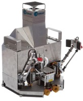
I mentioned this in another post yesterday - I use a 25mm fan tucked between the hot end mount and delta plate:
[img]http://mhackney.zenfolio.com/img/s8/v75 ... 2480-3.jpg[/img]
It is a perfect press fit, no glue or anything holding it in. You could always use a set screw from the top. I have it wired to my LEDs so when I flip them on, the fan is on. It is aimed directly at the PEEK section of the hot end and blows quite a bit of air
I took some temperature measurements to show the efficacy of this fan and arrangement:
With the hot end heated to 220°C and my thermocouple held by a small piece of Kapton tape in the lower groove cut in the PEEK barrel on the backside opposite the fan, I let it stabilize for 15 minutes.
1) initial measurement before fan turned on: 120°C
2) fan turned on, temp immediately started dropping. In 1 minute the temp was 70°C
3) fan turned off, temp immediately started climbing, in 30 seconds it was back up to 200°C and in 1 minute, 220°C
So, I am happy with the cooling effect of this little fan. I have not taken similar measurements of the larger 40mm fan I use on my H-1 and H-1.1 but I think this little guy puts out more volume in a focused area than those larger fans.
regards,
Michael
Sublime Layers - my blog on Musings and Experiments in 3D Printing Technology and Art
Start Here:
A Strategy for Successful (and Great) Prints
Strategies for Resolving Print Artifacts
The Eclectic Angler

Re: Mhackney's Rostock Max
Michael, could you post mfr, part number, and/or specs for that 25mm fan?
- dan
- dan
Re: Mhackney's Rostock Max
I'm going to be offering these on my site in 3-4 weeks but:
ADDA
AD0212MX-K53
DC 12v 0.06Amp
25mm x 6.5mm
ADDA
AD0212MX-K53
DC 12v 0.06Amp
25mm x 6.5mm
Sublime Layers - my blog on Musings and Experiments in 3D Printing Technology and Art
Start Here:
A Strategy for Successful (and Great) Prints
Strategies for Resolving Print Artifacts
The Eclectic Angler
Re: Mhackney's Rostock Max
Why do you have this fan? Will it improve the print quality (blobbing?) or is it just do extend the lifetime of the teflon liners? Or is it maybe only usefull for PLA in any way?
Thanks in advance!
Thanks in advance!
Re: Mhackney's Rostock Max
If you print with PLA you will find you need a fan on the cold zone to prevent creep and the consequential plugging. I also find it does no harm to keep the zone cool even for ABS. In fact, several commercial extruder/hotend combos have a built in fan to keep the cool zone cool. I doubt that it helps prevent blobbing or extend the teflon tubing life if you are working within reasonable temp ranges.
Sublime Layers - my blog on Musings and Experiments in 3D Printing Technology and Art
Start Here:
A Strategy for Successful (and Great) Prints
Strategies for Resolving Print Artifacts
The Eclectic Angler
-
Craftgizmos
- Printmaster!
- Posts: 45
- Joined: Sat Nov 24, 2012 1:00 pm
Re: Mhackney's Rostock Max
Hi Mhackney -
What have you discovered is the easiest way to up-snap the rods from the aluminum u-bolts? I'm in the same place now, realizing I have to very carefully fit the mating surfaces. I have to smooth everything out so I'm loosening the screws that hold the axles on the cheapskates and sliding them out to remove the mostly assembly carriage. I got one rod off, but it was a struggle and I'm trying to be as careful as I can so I don't do any misc damage.
What about using a drill countersink bit in your fingers instead of the exacto to create the small bevel at the holes in the rod ends?
Thanks!
Re: Mhackney's Rostock Max
I did basically the same thing when I redid mine. Don't use any metal tools to pry! I twisted the arm and used a plastic credit card to lift one side of the U on the arm off the pivot point on the aluminum part. That worked pretty well.
I felt I had more control scraping with an exacto blade. With a drill, you are going to get a hole the size of the bit and if it's too big you can't go back. Scraping removes such a small amount of material that it took several passes. The other thing is, the scraping also removes the burr and fuzz nicely without enlarging the hole.
I felt I had more control scraping with an exacto blade. With a drill, you are going to get a hole the size of the bit and if it's too big you can't go back. Scraping removes such a small amount of material that it took several passes. The other thing is, the scraping also removes the burr and fuzz nicely without enlarging the hole.
Sublime Layers - my blog on Musings and Experiments in 3D Printing Technology and Art
Start Here:
A Strategy for Successful (and Great) Prints
Strategies for Resolving Print Artifacts
The Eclectic Angler
Re: Mhackney's Rostock Max
Well I guess I got lucky pulling mine off! I just used a pair of pliers and twisted the end and gently pulled until it came loose. Also making sure to not move any of the delta arms much (or at least very fast) because I was too lazy to disconnect the motors from the RAMBo. I'm like everyone else though, I wish there was an "easy" way to adjust those u-joints... I just used a 1" wide metal file to do the "heavy" work, then 220 grit sandpaper as it got closer to free movement without side to side play. I also did like mhackney, once I thought I was close with the 220 grit, I just left the u-joint in place tightented down (the resistance can/will change when tightened down). Then pivoted it and used an exacto knife to lightly scrape where I thought there was resistancemhackney wrote:I did basically the same thing when I redid mine. Don't use any metal tools to pry! I twisted the arm and used a plastic credit card to lift one side of the U on the arm off the pivot point on the aluminum part. That worked pretty well.
I felt I had more control scraping with an exacto blade. With a drill, you are going to get a hole the size of the bit and if it's too big you can't go back. Scraping removes such a small amount of material that it took several passes. The other thing is, the scraping also removes the burr and fuzz nicely without enlarging the hole.
DIY instructions/videos/hardware links:
Carbon fiber rods w/ ball joints for Rostock MAX ~$40 http://forum.seemecnc.com/viewtopic.php?f=36&t=2165
Carbon fiber rods w/ ball joints for Rostock MAX ~$40 http://forum.seemecnc.com/viewtopic.php?f=36&t=2165
-
Craftgizmos
- Printmaster!
- Posts: 45
- Joined: Sat Nov 24, 2012 1:00 pm
Re: Mhackney's Rostock Max
Thank you for the input.
I'll work on it. I'll try something with a credit card wedge. If I could, I'd print something
I'll work on it. I'll try something with a credit card wedge. If I could, I'd print something
-
Highcooley
- Printmaster!
- Posts: 121
- Joined: Sun Nov 18, 2012 10:23 am
Re: Mhackney's Rostock Max
Did you actually tweak your extruder acceleration and motor current settings any further meanwhile, or have you settled with 2250 / 222 ?aehM_Key wrote:Thanks for your info as well. I've set EXT0_MAX_ACCELERATION to 2250 and with the combination of 222 current, was it looking good so far.
(But not extensively tested.)