Glad you got it working!
Carl
Mhackney's Rostock Max
-
Eaglezsoar

- ULTIMATE 3D JEDI
- Posts: 7159
- Joined: Sun Apr 01, 2012 5:26 pm

Re: RAMPS redux
mhackney wrote:Well, chalk this problem up to "operator error". Basically, I thought this RAMPS had Pololu stepper drivers like my first RAMPS. It doesn't, it has StepSticks. The current limiting pot / circuit is not the same as the Pololu! I thought I had set the stepper current to .9A but it was actually set to something like .2A. Doh!
Anyway, it is fully operational on RAMPS now. And my new replacement RAMBo arrives tomorrow. And, the parts I ordered to try to fix my broken RAMBo arrived today! Too many controllers, too few printers.
Sounds like your just gonna have to build another printer.

Re: Mhackney's Rostock Max
Yeah, I have 3 now. I do want another delta though. Considering a scratchbuilt with a few bells and whistles.
Sublime Layers - my blog on Musings and Experiments in 3D Printing Technology and Art
Start Here:
A Strategy for Successful (and Great) Prints
Strategies for Resolving Print Artifacts
The Eclectic Angler
RAMBo 2
The sequel:
[img]http://mhackney.zenfolio.com/img/s9/v92 ... 9796-3.jpg[/img]
The new RAMBo came in today. I am going to go ahead and install it, it has fan control and supports 2 extruders at the same time. The RAMPS has 3 MOSFET outputs and I would need 4. I have other uses for the RAMPs anyway.
[img]http://mhackney.zenfolio.com/img/s9/v92 ... 9796-3.jpg[/img]
The new RAMBo came in today. I am going to go ahead and install it, it has fan control and supports 2 extruders at the same time. The RAMPS has 3 MOSFET outputs and I would need 4. I have other uses for the RAMPs anyway.
Sublime Layers - my blog on Musings and Experiments in 3D Printing Technology and Art
Start Here:
A Strategy for Successful (and Great) Prints
Strategies for Resolving Print Artifacts
The Eclectic Angler
Max Mods
My new RAMBo came in today so I thought I would take this opportunity to button down the wiring and permanently mount my 2 power supplies in the base (a 12V and a 24V supply). I also want to mount the RAMBo in a stationary position so I am not straining the wiring when I open/close the door.
I'm starting at the power supply bay. First I temporarily removed the skirt support so I could remove the unused stock power supply mount. I simply loosened a few stews top and bottom and was able to separate the base enough to pop it out.
[img]http://mhackney.zenfolio.com/img/s8/v75 ... 1436-3.jpg[/img]
I removed the screws and then sawed the power supply partition to remove it:
[img]http://mhackney.zenfolio.com/img/s8/v77 ... 1494-3.jpg[/img]
After replacing the skirt support, there is a lot more room in the bay:
[img]http://mhackney.zenfolio.com/img/s8/v75 ... 1436-3.jpg[/img]
Plenty of room for both supplies:
[img]http://mhackney.zenfolio.com/img/s9/v90 ... 1538-3.jpg[/img]
I will mount these with the fans facing out, so the supplies will be bottom-to-bottom. They will have about a 1/2" gap between them. I'm fabricating an aluminum mount that will screw to the bottom edge of the supplies with 1/2" standoffs so I get airflow underneath too. This will be secured to the bottom Melamine plate with a couple of easily accessible screws so removing the supplies will be easy. These supplies do not generate a lot of heat in continuous operation so I don't anticipate needing a fan in the base. But there is room for one in needed.
I also removed the two doors by loosening screws and popping them out. I switched the locations of the two doors so the LCD will be between the X and Y columns. The RAMBo will be mounted in this bay too so all the electronics are in one location. This way, the second extruder arm (I have the Add-A-Struder kit) won't interfere with the LCD display.
Sublime Layers - my blog on Musings and Experiments in 3D Printing Technology and Art
Start Here:
A Strategy for Successful (and Great) Prints
Strategies for Resolving Print Artifacts
The Eclectic Angler
RAMBo reloco
Here's the relocated LCD door:
[img]http://mhackney.zenfolio.com/img/s8/v75 ... 4714-3.jpg[/img]
and the relocated RAMBo door (I flipped it over so the labels are now inside):
[img]http://mhackney.zenfolio.com/img/s9/v86 ... 4854-3.jpg[/img]
Now the 2nd extruder arm is not in the way of anything.
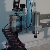
And here is what I have in mind for the RAMBo itself:
[img]http://mhackney.zenfolio.com/img/s8/v74 ... 4952-3.jpg[/img]
(don't panic, this is my dead RAMBo so the blue tape will do not harm!)
Basically, I cut a piece of 1/4" phenolic a little longer than the RAMBo. The RAMBo will be mounted to it with standoffs and the phenolic tapped for the screws. A piece of 1" aluminum angle is attached to the bottom. Two quick release screws will secure the angle to the base. All of the wiring can come in from behind and over the top or around the sides for attachment. If I need to remove the RAMBo, the quick release screws are removed and the entire assembly can pull out.
Now that I've mocked it up, I may make the mounting plate 1/2" larger on each of the three sides (not the base) so I can drill holes to use zip ties to secure the wiring. I'll sleep on that and fabricate something up tomorrow.
[img]http://mhackney.zenfolio.com/img/s8/v75 ... 4714-3.jpg[/img]
and the relocated RAMBo door (I flipped it over so the labels are now inside):
[img]http://mhackney.zenfolio.com/img/s9/v86 ... 4854-3.jpg[/img]
Now the 2nd extruder arm is not in the way of anything.
And here is what I have in mind for the RAMBo itself:
[img]http://mhackney.zenfolio.com/img/s8/v74 ... 4952-3.jpg[/img]
(don't panic, this is my dead RAMBo so the blue tape will do not harm!)
Basically, I cut a piece of 1/4" phenolic a little longer than the RAMBo. The RAMBo will be mounted to it with standoffs and the phenolic tapped for the screws. A piece of 1" aluminum angle is attached to the bottom. Two quick release screws will secure the angle to the base. All of the wiring can come in from behind and over the top or around the sides for attachment. If I need to remove the RAMBo, the quick release screws are removed and the entire assembly can pull out.
Now that I've mocked it up, I may make the mounting plate 1/2" larger on each of the three sides (not the base) so I can drill holes to use zip ties to secure the wiring. I'll sleep on that and fabricate something up tomorrow.
Sublime Layers - my blog on Musings and Experiments in 3D Printing Technology and Art
Start Here:
A Strategy for Successful (and Great) Prints
Strategies for Resolving Print Artifacts
The Eclectic Angler
-
foshon

- Printmaster!
- Posts: 600
- Joined: Fri Mar 08, 2013 3:05 pm
- Location: Just to the right of SeeMeCNC
Re: Mhackney's Rostock Max
That RAMBo mount looks super clean, very nice!. I did something similiar with my 24v supply, I ommitted the second door and mounted to the bottom of the unit via some bolts I had laying around.
Purple = sarcasm
Please do a board search before posting your question, many have been answered with very time consuming detail already.
Please do a board search before posting your question, many have been answered with very time consuming detail already.
Re: Mhackney's Rostock Max
Here's the end result, not mounted yet.
[img]http://mhackney.zenfolio.com/img/s9/v93 ... 4520-3.jpg[/img]
I am thinking of mounting it off to the side. In the middle like I thought requires too much wire bending to reach the terminals.
[img]http://mhackney.zenfolio.com/img/s9/v92 ... 4600-4.jpg[/img]
[img]http://mhackney.zenfolio.com/img/s9/v93 ... 4520-3.jpg[/img]
I am thinking of mounting it off to the side. In the middle like I thought requires too much wire bending to reach the terminals.
[img]http://mhackney.zenfolio.com/img/s9/v92 ... 4600-4.jpg[/img]
Sublime Layers - my blog on Musings and Experiments in 3D Printing Technology and Art
Start Here:
A Strategy for Successful (and Great) Prints
Strategies for Resolving Print Artifacts
The Eclectic Angler
2-up Power Supply Mount
Here is the bracket I whipped together. The supplies are 3/4" apart and staggered so I can reach the terminal screws easily.
[img]http://mhackney.zenfolio.com/img/s8/v85 ... 2278-3.jpg[/img]
And here they are in position:
[img]http://mhackney.zenfolio.com/img/s8/v84 ... 2360-3.jpg[/img]
There is a hold down in the back that the bracket slides into to hold the back and the front is screwed to the base. I can reach all terminals for wiring. I did delete the surround spacer next to the Z column in order to pull this off but there is plenty of sub-structure to support the table.
I can mount an on/off switch, fuse and cord socket to the right of the supplies.
Sublime Layers - my blog on Musings and Experiments in 3D Printing Technology and Art
Start Here:
A Strategy for Successful (and Great) Prints
Strategies for Resolving Print Artifacts
The Eclectic Angler

Re: Mhackney's Rostock Max
Why did you decide not to mount it to the interior divider using T-nuts? I moved mine there once I saw they're making mounting holes for that now. Seems clean enough, and the wiring is all easily accessible.
- dan
- dan
Re: Mhackney's Rostock Max
A couple of reasons Dan, mostly, I want to be able to get access/remove the board easily. I'm experimenting with dual extruders, direct drive extruders, etc and plugging in the connectors is a pain with the board fixed. I also want to have good airflow around the RAMBo with an extra fan for cooling. It also looked like getting in there to drill the holes with my machine assembled was going to be a PIA too. Did your's have the holes there already?
Sublime Layers - my blog on Musings and Experiments in 3D Printing Technology and Art
Start Here:
A Strategy for Successful (and Great) Prints
Strategies for Resolving Print Artifacts
The Eclectic Angler
Re: Mhackney's Rostock Max
No, mine didn't have the holes already. I drilled them while I had the power supply out for replacement.
- dan
- dan
Salvaged thermistor port
Well, I may be on the right path. I suspected the small caps on the thermistor circuits on the RAMBo might have blown on my board. I replaced the cap on the original heated bed port that I blew over a month ago and it now works. This tells me that the Arduino muxed input for the thermistor pins is probably ok. I'll be interested to see if I can resurrect the other 3 ports.
Sublime Layers - my blog on Musings and Experiments in 3D Printing Technology and Art
Start Here:
A Strategy for Successful (and Great) Prints
Strategies for Resolving Print Artifacts
The Eclectic Angler
-
MorbidSlowBurn

- Printmaster!
- Posts: 169
- Joined: Sun Mar 03, 2013 5:33 pm
Re: Mhackney's Rostock Max
Take good notes and pictures. I see another sticky as this has happened to a couple of RAMBO's. Always look forward to your write-ups.
Re: Mhackney's Rostock Max
are the caps the little bitty sqaure ones next to the thermistor headers. if they are those things are awfully small.
My rostock build log http://forum.seemecnc.com/viewtopic.php?f=42&t=1228
Re: Mhackney's Rostock Max
@MorbidSlowBurn, thanks and will do. I will photo the sequence for the next port.
Sublime Layers - my blog on Musings and Experiments in 3D Printing Technology and Art
Start Here:
A Strategy for Successful (and Great) Prints
Strategies for Resolving Print Artifacts
The Eclectic Angler

Re: Mhackney's Rostock Max
What are the values for those littleguys and if you don't mind could you snap a quick pic of the suspected components. Since I have a few rambo's here I could sacrific one to attempt the transplant or on of my scrap boards in my junk bin.
Thanks man.
Thanks man.
"Now you see why evil will always triumph! Because good is dumb." - Spaceballs
Re: Mhackney's Rostock Max
@Flateric - here's a photo of the parts placement:
This is the part from Digikey. I'd suggest waiting a couple of days until I can get to the other ones and see if this is indeed a fix or if the ATMega will need to be replaced too.
Sublime Layers - my blog on Musings and Experiments in 3D Printing Technology and Art
Start Here:
A Strategy for Successful (and Great) Prints
Strategies for Resolving Print Artifacts
The Eclectic Angler
Re: Mhackney's Rostock Max
Do you already have an idea how to put the bootloader on the chip?mhackney wrote:if this is indeed a fix or if the ATMega will need to be replaced too.
Re: Mhackney's Rostock Max
I have friends in high places!
That will be a bit of a challenge but I have a few EE friends who know how to do this.
That will be a bit of a challenge but I have a few EE friends who know how to do this.
Sublime Layers - my blog on Musings and Experiments in 3D Printing Technology and Art
Start Here:
A Strategy for Successful (and Great) Prints
Strategies for Resolving Print Artifacts
The Eclectic Angler
Re: Mhackney's Rostock Max
Ok, perfect, just wanted to make sure, that you thought about this point 
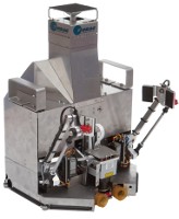
Cool Running
Well, I got my new mounting for the RAMBo completed and the wiring redone. There is plenty of airflow all around the RAMBo and it stays nice and cool.
[img]http://mhackney.zenfolio.com/img/s9/v91 ... 8312-4.jpg[/img]
I'm pleased with the setup. Easy to get to the jacks to plug things in and out and no strain on the wiring. The fan for the power supplies in the next compartment actually draws air through the RAMBo compartment too.
[img]http://mhackney.zenfolio.com/img/s9/v91 ... 8312-4.jpg[/img]
I'm pleased with the setup. Easy to get to the jacks to plug things in and out and no strain on the wiring. The fan for the power supplies in the next compartment actually draws air through the RAMBo compartment too.
Sublime Layers - my blog on Musings and Experiments in 3D Printing Technology and Art
Start Here:
A Strategy for Successful (and Great) Prints
Strategies for Resolving Print Artifacts
The Eclectic Angler
-
Eaglezsoar
- ULTIMATE 3D JEDI
- Posts: 7159
- Joined: Sun Apr 01, 2012 5:26 pm
Re: Mhackney's Rostock Max
That's a good clean look. The added splash of red on the back of the Rambo looks cool.
Good job!
Good job!
Build Plate Update
See Adjustable Build Plate Design
The three MIC-6 aluminum disks I ordered arrived today:
[img]http://mhackney.zenfolio.com/img/s9/v93 ... 3874-3.jpg[/img]
[img]http://mhackney.zenfolio.com/img/s8/v75 ... 3488-3.jpg[/img]
They are, as MIC-6 should be, flat. They are 5/16" thick and 16 3/4" diameter. They will be milled down as to make the micro-adjustable build surface shown in the link above. My ONLY concern with these are their mass and the amount of power it will take to heat these up. They weigh 7# each. Of course they will be a little lighter when they are cut down to 13" diameter, but still a big item that can't be shipped flat rate priority.
Sublime Layers - my blog on Musings and Experiments in 3D Printing Technology and Art
Start Here:
A Strategy for Successful (and Great) Prints
Strategies for Resolving Print Artifacts
The Eclectic Angler
Re: Mhackney's Rostock Max
kool when can i order one. do i get a loyal customer discount =P
i haven't had a chance to test my 3/8 mic6 plate yet, i'm having too much fun playing around with my printer now that its somewhat dialed in.
check it out
i haven't had a chance to test my 3/8 mic6 plate yet, i'm having too much fun playing around with my printer now that its somewhat dialed in.
check it out
- Attachments
-
Last edited by cambo3d on Thu Apr 11, 2013 2:51 am, edited 2 times in total.
My rostock build log http://forum.seemecnc.com/viewtopic.php?f=42&t=1228