
Just messing around with a FLIR E6.
If you want anything specific, just let me know. I'm working on getting video of the heat up.
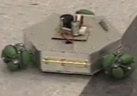
Bed set to 60C. The outer rings overshoot a bit while the center plays catch up. This was taken without the glass on.
[img]http://i482.photobucket.com/albums/rr18 ... IR0003.jpg[/img]
[img]http://i482.photobucket.com/albums/rr18 ... IR0008.jpg[/img]
The stock wiring from the controller to the heated bed is not up to par for the job.
[img]http://i482.photobucket.com/albums/rr18 ... IR0006.jpg[/img]
[img]http://i482.photobucket.com/albums/rr18 ... IR0007.jpg[/img]
Thermal images of the Rostock Max v2
-
BenTheRighteous
- Printmaster!
- Posts: 695
- Joined: Fri Nov 07, 2014 9:38 am
Re: Thermal images of the Rostock Max v2
Very interesting - are you sure you're able to draw the conclusion that hot wires = insufficient gauge? Maybe the wires are hot because they're connected to something hot?
nitewatchman wrote:it was much cleaner and easier than killing a chicken on top of the printer.
Re: Thermal images of the Rostock Max v2
That's a good point, ill try to get another picture after this print. I'll let everything cool down and try to catch it heating up. Looking over my test video, it looks like the wires get hot from the controller side first; It's just not that clear to be definitive.
update:
It's been printing a while and temp saturated. Although you can see the two power wires going up to the hole. The middle is currently cooler than both ends. Just not sure if the connector side is pulling heat from the board.
[img]http://i482.photobucket.com/albums/rr18 ... IR0016.jpg[/img]
Smoothieboard:
[img]http://i482.photobucket.com/albums/rr18 ... IR0015.jpg[/img]
Re: Thermal images of the Rostock Max v2
Okay, no doubt about it at all. The power wires to the bed light up well before the bed even hits 40c.
[img]http://i482.photobucket.com/albums/rr18 ... IR0022.jpg[/img]
[img]http://i482.photobucket.com/albums/rr18 ... IR0020.jpg[/img]
[img]http://i482.photobucket.com/albums/rr18 ... IR0021.jpg[/img]
[img]http://i482.photobucket.com/albums/rr18 ... IR0022.jpg[/img]
[img]http://i482.photobucket.com/albums/rr18 ... IR0020.jpg[/img]
[img]http://i482.photobucket.com/albums/rr18 ... IR0021.jpg[/img]
Re: Thermal images of the Rostock Max v2
Video of the bed heating up. Please disregard the focal distance of the dual camera. Was slightly off until the distance was adjusted, still learning the features and settings.
[youtube]http://www.youtube.com/watch?v=oQEl9LI4b2E[/youtube]
[youtube]http://www.youtube.com/watch?v=oQEl9LI4b2E[/youtube]
Re: Thermal images of the Rostock Max v2
That is awesome!
Having wired household and commercial/industrial circuits for the expected and appropriate load, I have never looked at the heat an appropriately sized wire will reach at full load/draw.
Recognizing that there are different types of wire insulation and you can have copper and aluminum wiring, what is an appropriate working temperature of a fully loaded wire.
My 3D-Printing learning curve is asymptotic to a Delta's X, Y and Z-axes
Re: Thermal images of the Rostock Max v2
Looked this up and as mentioned the different types of wires and insulation (THHN, THHW, etc) for copper or aluminum have temp ratings of wire temperature ratings of 60°, 75°, and 90° C. The higher the temperature rating, the greater the amp draw for a given AWG size.
Regardless heat is due to resistance and thus results in a loss of voltage. Makes me wonder if poor heating of the bed as noted by some is due in part to this. If you cut it break off a few strands of copper wire during the build you could affect the resistance and drop the voltage.
Regardless heat is due to resistance and thus results in a loss of voltage. Makes me wonder if poor heating of the bed as noted by some is due in part to this. If you cut it break off a few strands of copper wire during the build you could affect the resistance and drop the voltage.
My 3D-Printing learning curve is asymptotic to a Delta's X, Y and Z-axes
Re: Thermal images of the Rostock Max v2
Very good work. This is some very useful information.
*not actually a robot
-
bvandiepenbos

- Printmaster!
- Posts: 923
- Joined: Thu Apr 05, 2012 11:25 pm
- Location: Goshen, IN
- Contact:
Re: Thermal images of the Rostock Max v2
Thanks KAS this is very useful data.
FWIW I have always used heavier wire than stock, either 14 gauge stranded copper or double up the stock 18 gauge. It would be interesting to see if heavier runs cooler.
Another thing I would like to see is thermal image of bed with aluminum heat spreader disk in place.
My experience has been the bed temperature is within 2-3 c with the plate and up to 15 c difference from center to edges without.
This is with 1/16" thick 5052 aluminum.
It does not have enough mass to slow down heat up, actually it heats up faster.
The heat spreader plate is something I have been meaning to cut up a small batch to see if anybody would be interested, but have not had the time yet.
I run a heat spreader on all my machines and have cut a few for others. People report that they work well.
~*Brian V.
RostockMAX v2 (Stock)
MAX METAL "ShortyMAX"
MAX METAL Rostock MAX Printer Frame
NEMESIS Air Delta v1 & v2 -Aluminum delta printers
Rostock MAX "KITT" - Tri-Force Frame
GRABER i3 "Slim"
RostockMAX v2 (Stock)
MAX METAL "ShortyMAX"
MAX METAL Rostock MAX Printer Frame
NEMESIS Air Delta v1 & v2 -Aluminum delta printers
Rostock MAX "KITT" - Tri-Force Frame
GRABER i3 "Slim"
Re: Thermal images of the Rostock Max v2
Tomorrow I'll solder on a thicker gauge to compare for any differences.
Below are my current heating times, I'm guessing that's pretty normal for the default 12v power supplies.
Starting temp 26c, 18awg, stock power supply, borosilicate glass with .04 PEI layer.
40c 1:47
50c 2:54
60c 4:12
70c 5:44
80c 7:38
Below are my current heating times, I'm guessing that's pretty normal for the default 12v power supplies.
Starting temp 26c, 18awg, stock power supply, borosilicate glass with .04 PEI layer.
40c 1:47
50c 2:54
60c 4:12
70c 5:44
80c 7:38
Re: Thermal images of the Rostock Max v2
To make sure and clarify the above.3D-Print wrote: Regardless heat is due to resistance and thus results in a loss of voltage. Makes me wonder if poor heating of the bed as noted by some is due in part to this. If you cut it break off a few strands of copper wire during the build you could affect the resistance and drop the voltage.
V=IR. Ohms law dictates that an increase in resistance would result in a loss of current (I) if voltage is fixed (the caviat). Not a drop in voltage as noted above (unless the power unit current is maxed). Regardless, a loss of current would still cause the problem. I'm not sure exactly, but suspect our power units are relatively maxed In regard to V and possibly limited by current.
KAS, will be interesting to see you experiment results.
My 3D-Printing learning curve is asymptotic to a Delta's X, Y and Z-axes
Re: Thermal images of the Rostock Max v2
I disagree about the stock wiring not being up to par, even if it's not up to your expectations. For the load involved, the wire is staying within a safe temperature in operation. Wire temperatures in the neighborhood of 50C aren't a problem...that's still cold enough to touch and hold with bare fingers.
18 AWG copper is about 6.5 Ω per 1000 feet at 25C. Temperature is a factor, so at 50C it's 7.1 Ω per 1000 feet. Either way, that's a very small resistance for the actual length involved in this case. Still you're putting a fair amount of current though it, Power = Current squared times Resistance, so even that tiny number means you're dropping a couple watts of heat into the two wires. Some wire heat above the ambient temperature of the electronics box is to be expected.
16 AWG is 4.1 Ω and 14 AWG is 2.6 Ω, per 1000 feet at 25C. So yes, upping the wire side will reduce the resistance and result in less heat generated in the wires. So it's a fine upgrade if you want to do it. It's just not required.
Re: Thermal images of the Rostock Max v2
Eric wrote:I disagree about the stock wiring not being up to par, even if it's not up to your expectations. For the load involved, the wire is staying within a safe temperature in operation. Wire temperatures in the neighborhood of 50C aren't a problem...that's still cold enough to touch and hold with bare fingers.
18 AWG copper is about 6.5 Ω per 1000 feet at 25C. Temperature is a factor, so at 50C it's 7.1 Ω per 1000 feet. Either way, that's a very small resistance for the actual length involved in this case. Still you're putting a fair amount of current though it, Power = Current squared times Resistance, so even that tiny number means you're dropping a couple watts of heat into the two wires. Some wire heat above the ambient temperature of the electronics box is to be expected.
16 AWG is 4.1 Ω and 14 AWG is 2.6 Ω, per 1000 feet at 25C. So yes, upping the wire side will reduce the resistance and result in less heat generated in the wires. So it's a fine upgrade if you want to do it. It's just not required.
I'm not a electronics guy by any means. I just saw the wires heat up and didn't think that was optimal. Also, they get much hotter than 50c, that's just the hottest spot when I took that picture.
I just soldered 14awg 600v rated wire and they light up like a toaster as-well. Since I only measured ambient to 80c once on each wire size, I'd take these results with a grain of salt.
I'll have to agree with Eric and others, that no obvious benefit was made by changing 18awg to 14awg.
Starting temp 26c, 18awg, stock power supply
40c 1:47
50c 2:54
60c 4:12
70c 5:44
80c 7:38
Starting temp 25c, 14awg solid 600v rated, stock power supply
40c 2:03
50c 3:14
60c 4:36
70c 6:14
80c 8:20
I was surprised that it took longer to heat-up. Possible that the 14awg was acting as a heat sink?
I'll let everything cool down then record the thermal video. Then I'll be taking the 14awg off and putting something a little more flexible.(that's a bit to stiff to work with)
Re: Thermal images of the Rostock Max v2
....and then *BAM*! Science!
You guys are awesome.
g.
You guys are awesome.
g.
Delta Power!
Defeat the Cartesian Agenda!
http://www.f15sim.com - 80-0007, The only one of its kind.
http://geneb.simpits.org - Technical and Simulator Projects
Defeat the Cartesian Agenda!
http://www.f15sim.com - 80-0007, The only one of its kind.
http://geneb.simpits.org - Technical and Simulator Projects
Re: Thermal images of the Rostock Max v2
Agree science rules. You learn everyday. Thanks for pointing out and reminding me of the minimal loss due to that darn exponential power equation.geneb wrote:....and then *BAM*! Science!
You guys are awesome.
g.
My 3D-Printing learning curve is asymptotic to a Delta's X, Y and Z-axes
-
IMBoring25
- Printmaster!
- Posts: 616
- Joined: Wed Mar 18, 2015 1:11 am
Re: Thermal images of the Rostock Max v2
You're looking at the circuit as a whole. The previous poster was looking at elements of a series circuit. If we consider the Rambo terminals as a black-box 12V source, the circuit you're thinking of containing just the bed could also be construed as containing as many as six additional resistive circuit elements, wired in series (neglecting for the moment the parallel LED/resistor circuit).3D-Print wrote:To make sure and clarify the above.3D-Print wrote: Regardless heat is due to resistance and thus results in a loss of voltage. Makes me wonder if poor heating of the bed as noted by some is due in part to this. If you cut it break off a few strands of copper wire during the build you could affect the resistance and drop the voltage.
V=IR. Ohms law dictates that an increase in resistance would result in a loss of current (I) if voltage is fixed (the caviat). Not a drop in voltage as noted above (unless the power unit current is maxed). Regardless, a loss of current would still cause the problem. I'm not sure exactly, but suspect our power units are relatively maxed In regard to V and possibly limited by current.
KAS, will be interesting to see you experiment results.
The solder joints, wires, and screw terminal connections all have resistances associated with them and they will dissipate some of the voltage supplied by that 12V source, converting it to heat and lowering the voltage dissipated in the bed. The current flowing through this series circuit will reflect 12V against the sum of the resistances and the voltage and power dissipated in each circuit element will be based on the proportion of the total resistance each circuit element represents.
Re: Thermal images of the Rostock Max v2
These pictures are awesome!
A couple notes:
1) the wires are heating more than I would like. any power lost in the wires is power not heating the bed. Plus it will contribute to heating the connectors. I am finally upgrading to that 750W corsair today, I am going to upgrade those wires while I am at it.
2) The smoothie board was getting hot. while it looks all within spec, as an EE I try to avoid having that much heat on my boards, as it reduces reliability and life. A fan or directing more air over the smoothieboard is the solution.
Gee, we have this nice 3d printer, it could print some great ductwork to put the moving air where it is most needed.
3) I would like to see what the steppers (x,y,z, and extruders) look like when printing a long job.
4) I would like to see what the print head looks like when printing. Probably get the object we are printing in the same picture, that might be interesting too. What is the Max temp that the FLIR camera can distinguish?
Re: Thermal images of the Rostock Max v2
Haha this is so double triple awesome.
*not actually a robot
Re: Thermal images of the Rostock Max v2
That ball of hot mess is the 14awg solid wire from the smoothieboard to the Onyx bed. Also two separate power supply wires from the stock supply. The 14awg is to hard to work with so I'm going to try stranded 16awg next.
I'll also get the steppers( .9 degree installed and they appear to run cooler than stock), Extruder(stock), Hotend(prometheus), Onyx with & without glass, carbon fiber heat spreader and soon an aluminium spreader, also printing stuff.
[youtube]http://www.youtube.com/watch?v=N3h4zyoNJUQ[/youtube]
I'll also get the steppers( .9 degree installed and they appear to run cooler than stock), Extruder(stock), Hotend(prometheus), Onyx with & without glass, carbon fiber heat spreader and soon an aluminium spreader, also printing stuff.
[youtube]http://www.youtube.com/watch?v=N3h4zyoNJUQ[/youtube]
Re: Thermal images of the Rostock Max v2
Have you measured the temp of those wires after the bed is up to temp and its maintaining? I imagine it would depend on the temperature since mine holds about 95% power at 90C and less at lower temps.
Re: Thermal images of the Rostock Max v2
JFettig wrote:Have you measured the temp of those wires after the bed is up to temp and its maintaining? I imagine it would depend on the temperature since mine holds about 95% power at 90C and less at lower temps.
I'll try that now since the bed is still hot.
16AWG stranded wire
[youtube]http://www.youtube.com/watch?v=8dTOWAZDyyU[/youtube]
edit: image of the bed sitting at 80c for about 20min everything inside is saturated with heat. It's hard to tell what's really happening because the FLIR automatically calibrates the color scale. While the wires look cooler, it's still in the upper ranges closer to the bed temp.
The transistor that controls the bed on the smoothieboard gets up to 80-90c. Is it normal to not put a heat-sink on something like that?
- FLIR0031.jpg (151.7 KiB) Viewed 15651 times
Re: Thermal images of the Rostock Max v2
The outside ring of your bed doesn't get that hot, so the edge-on view is a poor indicator of bed temperature as well.
When you stick your hand in the video, it gives a nice thermal reference point. Surface temperature of your hand should be about 30-35C.
On Mosfets you'd need to check the datasheet for that part, but the upper temperature is usually over 120C. That said, if it's a through-hole part, heat sinks are easy to add, and putting one on the bed output can't hurt. Active cooling (fan moving air across board) is the other way to improve the situation.
Re: Thermal images of the Rostock Max v2
Just keep in mind the FLIR is displaying the temperature deferential and only within the retical portion. An ice cube in liquid nitrogen would appear to be on fire to the FLIR.Eric wrote:The outside ring of your bed doesn't get that hot, so the edge-on view is a poor indicator of bed temperature as well.

Re: Thermal images of the Rostock Max v2
eating popcorn... you guy are awesome, but now I want a FLIR too.... 
~PartDaddy
SeeMeCNC Owner & Founder
Blackpoint Engineering is SeeMeCNC
Since 1996
SeeMeCNC Owner & Founder
Blackpoint Engineering is SeeMeCNC
Since 1996
Re: Thermal images of the Rostock Max v2
Working with Brian from Trick Laser trying to capture the thermal signature of his new Aluminium Heat Spreader.
Each video was heated from room temp to 70c. When the bed thermistor bounced off 70c a few times, I turned the power off to the bed. ( I waved my hand across the screen when the power was cut).
I ended the video when the thermistor showed 50c.
ONYX PCB Heated Bed Only, No Glass
[youtube]http://www.youtube.com/watch?v=dOiNospa6oo[/youtube]
ONYX PCB Heated Bed, Borosilicate Glass.
[youtube]http://www.youtube.com/watch?v=Snr-Aug-vdI[/youtube]
Onyx PCB with Trick Laser Aluminium Heat Spreader No Glass
[youtube]http://www.youtube.com/watch?v=gLeh1selqDE[/youtube]
Onyx PCB Trick Laser Heat Spreader With Glass
[youtube]http://www.youtube.com/watch?v=UfjnDrnPUpI[/youtube]