Mhackney's Rostock Max

Re: Mhackney's Rostock Max
There is no voltage at the output terminal to the heated bed. There is 12V at the power input terminal. The LED does not come on - there is no power going to the bed. Firmware configured for pin 3 for heated bed output. This is correct according to the RAMBo pinout table.
Sublime Layers - my blog on Musings and Experiments in 3D Printing Technology and Art
Start Here:
A Strategy for Successful (and Great) Prints
Strategies for Resolving Print Artifacts
The Eclectic Angler
Heated Bed Output - Important Tip!
Gentleman, my and aehM_Key's suspicions were indeed correct - the hotend thermistor MUST BE connected (or perhaps disabled in firmware) in order for the heated bed circuitry to be enabled. Not sure where this is in the code but now that I know this is the case I'll look for it.
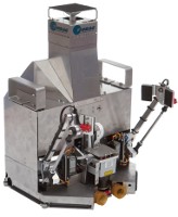
So, at this point, my heated bed is working fine! And it heats up quickly too, this power supply rocks. Less than 4 1/2 minutes to get to 85°C and that was with 2 ramps - 60° first and then up to 80°.
[img]http://mhackney.zenfolio.com/img/s8/v79 ... 2032-3.jpg[/img]
So, at this point, my heated bed is working fine! And it heats up quickly too, this power supply rocks. Less than 4 1/2 minutes to get to 85°C and that was with 2 ramps - 60° first and then up to 80°.
[img]http://mhackney.zenfolio.com/img/s8/v79 ... 2032-3.jpg[/img]
Sublime Layers - my blog on Musings and Experiments in 3D Printing Technology and Art
Start Here:
A Strategy for Successful (and Great) Prints
Strategies for Resolving Print Artifacts
The Eclectic Angler
Hot End Wiring
As reported in the last post, the hot end thermistor must be hooked up in order for the hot bed to work.
I used crimp connectors for the heating resistors. Don't solder these connections, they will fail and you'll have a mess if your lucky and short circuit and/or fire if not. Don't ask... (H-1 experience). I routed the wiring through the adapter plate.
[img]http://mhackney.zenfolio.com/img/s8/v83 ... 6452-3.jpg[/img]
I like to use thin wall small diameter teflon tubing (McMaster) to insulate the thermistor leads. It is just as important to have a solid connection on the terminator. If the leads break or disconnect during a run, the feedback loop will be broken and the RAMBo will continue to pump current to the hot end until it melts down. Don't ask...
[img]http://mhackney.zenfolio.com/img/s8/v77 ... 6142-3.jpg[/img]
I put a blob of silicone over the silicone holding the thermistor in place then push the ends of the teflon into that to secure them. Leave about 1/4" to 3/8" of lead exposed. I put a short (3/4") length of heat shrink tube over each of the teflon tubes and solder the white wires to the leads. Then I shrink the tube over the teflon tube and solder joint to make a clean, insulated connection.
[img]http://mhackney.zenfolio.com/img/s1/v47 ... 6284-3.jpg[/img]
I'll let the silicone cure overnight before testing the hot end. I've learned that it pays to be patient and let the the silicone cure on the hotend before pushing ahead! This is the one area of the build where bad things can happen if the connections fail or short.
cheers,
Michael
Sublime Layers - my blog on Musings and Experiments in 3D Printing Technology and Art
Start Here:
A Strategy for Successful (and Great) Prints
Strategies for Resolving Print Artifacts
The Eclectic Angler
Re: Mhackney's Rostock Max
I'm glad it worked out for you.
Is there any reason, why I shouldn't use the two remaining wires of the 4 conductor 18ga wire for the thermistor? (I'm not going to add a second hotend or LEDs.)
Is there any reason, why I shouldn't use the two remaining wires of the 4 conductor 18ga wire for the thermistor? (I'm not going to add a second hotend or LEDs.)
Re: Mhackney's Rostock Max
No reason at all, go ahead! I did this on my H-1. However, I did end up adding a fan to that and I plan to add a fan to mine. If you are planning to print with PLA you'll need one.
Sublime Layers - my blog on Musings and Experiments in 3D Printing Technology and Art
Start Here:
A Strategy for Successful (and Great) Prints
Strategies for Resolving Print Artifacts
The Eclectic Angler
All wired up and ready to calibrate
Finished off the wiring to the hot end and extruder stepper this morning during the raging blizzard! Tested heating the bed, hot end and moving all the steppers. Everything is ready to go!
Sublime Layers - my blog on Musings and Experiments in 3D Printing Technology and Art
Start Here:
A Strategy for Successful (and Great) Prints
Strategies for Resolving Print Artifacts
The Eclectic Angler
Z Axis movement question
When I home and then go to Z=0, the nozzle ends up about 181mm from the bed. Almost exactly 1/2 of the full travel of the Z for the Rostock. My configuration.h has:
#define X_MAX_LENGTH 363.0
#define Y_MAX_LENGTH 363.0
#define Z_MAX_LENGTH 363.0
8 microsteps on all axes.
Without measuring (eyeballing) X and Y seem to be traveling the right amount. A G0 X10 movement looks pretty darned close to 10mm. I'm very familiar with calibrating cartesian printers and I verified everything in configuration.h (I have eeprom disabled for now and verified that too). Given that X and Y move the correct amount, that tells me that all 3 delta axes are in the ballpark. So I have no idea why or what to do about Z moving half as far as it is told. Any suggestions? This is using the Repetier firmware that Halopend posted recently.
Regards,
Michael
Sublime Layers - my blog on Musings and Experiments in 3D Printing Technology and Art
Start Here:
A Strategy for Successful (and Great) Prints
Strategies for Resolving Print Artifacts
The Eclectic Angler
All axes are moving 1/2 as far
Well, I actually measured a 10mm movement in X and Y and it appears that they are only moving 1/2 the distance too (about 5mm).
So, the issue seems to be on all 3 axes. I enabled eeprom so I could verify settings. I've attached a screenshot here. Does anyone notice anything odd? It looks fine to me.
So, the issue seems to be on all 3 axes. I enabled eeprom so I could verify settings. I've attached a screenshot here. Does anyone notice anything odd? It looks fine to me.
Sublime Layers - my blog on Musings and Experiments in 3D Printing Technology and Art
Start Here:
A Strategy for Successful (and Great) Prints
Strategies for Resolving Print Artifacts
The Eclectic Angler
Problem solved!
Turns out that the 1.1 Rev of the RAMBo is 16 micro steps. I don't know how long this version has been out but it is what came with my kit. Simply changing:
#define MICRO_STEPS 16
in configuration.h solved the problem and I am now working on calibration.
#define MICRO_STEPS 16
in configuration.h solved the problem and I am now working on calibration.
Sublime Layers - my blog on Musings and Experiments in 3D Printing Technology and Art
Start Here:
A Strategy for Successful (and Great) Prints
Strategies for Resolving Print Artifacts
The Eclectic Angler
-
Eaglezsoar

- ULTIMATE 3D JEDI
- Posts: 7159
- Joined: Sun Apr 01, 2012 5:26 pm
Re: Problem solved!
What value should be in there?mhackney wrote:Turns out that the 1.1 Rev of the RAMBo is 16 micro steps. I don't know how long this version has been out but it is what came with my kit. Simply changing:
#define MICRO_STEPS 16
in configuration.h solved the problem and I am now working on calibration.
I assume it should be 8 but I need to be sure.
Re: Mhackney's Rostock Max
for rev 1 it is 8 for rev 1.1 like mine, it is 16 micro steps as I showed in the previous post.
Sublime Layers - my blog on Musings and Experiments in 3D Printing Technology and Art
Start Here:
A Strategy for Successful (and Great) Prints
Strategies for Resolving Print Artifacts
The Eclectic Angler
Z Calibration
These delta printers are a LOT easier to calibrate in Z and level than a cartesian printer.
First I set the Z height at 0,0,0. I moved the head using G0 X0 Y0 Z10 to make sure I didn't crash into the glass. Then with a sheet of paper (I use cigarette rolling paper - an old machinist trick, it is about .001" thick) under the nozzle I click down 1 mm at a time. In my case, I hit Z=0 before the nozzle touch the paper. So, I increased my X, Y and Z max lengths to 370 mm (a guess but I wanted them to be longer than the actual tower travel) in the Repetier firmware's configuration.h
#define X_MAX_LENGTH 370.0
#define Y_MAX_LENGTH 370.0
#define Z_MAX_LENGTH 370.0
Then I ran down to z=10mm again and clicked down 1 mm at a time until I was within a mm and switched to .1mm clicks. As I moved the paper back and forth under the nozzle, I clicked the .1mm button until the nozzle just touched the paper - you can feel it snag slightly. I looked at the Z display and it read 5.4mm. This means that the printer thinks the nozzle is 5.4 mm above the table glass but it is actually at 0. So, I simply subtract 5.4 mm from 370 in the config file:
#define X_MAX_LENGTH 370.0 - 5.4
#define Y_MAX_LENGTH 370.0 - 5.4
#define Z_MAX_LENGTH 370.0 - 5.4
This gives me Z=0 at the center of the table. I homed and went to Z=0 (G0 Z0) several times and checked with the paper to make sure it was correct and repeatable.
Next, I used the technique described at http://minow.blogspot.com.au to set the Z=0 at the X, Y and Z tower locations. I used the coordinates/tower points Gene lists in the manual.
Z Tower – X0 Y90
Y Tower – X63 Y-30
X Tower – X-78 Y-48
Starting with the Z tower, I issued the gcode: G0 X0 Y90 Z10 to make sure I stopped above the glass. Then I used the 1mm and .1mm buttons to lower the head until I reached 0 or touched the paper. You set Z=0 at the tower positions using the stop screw at the home switch. If the nozzle is above the glass when the firmware thinks it should be Z=0, then you need to screw the stop screw IN (clockwise from the top, the same motion as tightening a screw). If it reaches Z=0 but the firmware thinks it as above the table, you screw the stop screw OUT. This takes a little bit of practice. Start with 1 full turn and see what happens. After each stop screw adjustment, you Home and then issue the gcode to go to the tower location. Test and repeat the adjustment until the paper just snags the nozzle.
Do this with the Y and Z towers too. Once complete, test going to X=Y=Z=0 to make sure you are still at zero there and also retest the three tower location "0s". Mine was right on after one adjustment cycle.
Sublime Layers - my blog on Musings and Experiments in 3D Printing Technology and Art
Start Here:
A Strategy for Successful (and Great) Prints
Strategies for Resolving Print Artifacts
The Eclectic Angler
Auto Tuning the Hot End and Heated Bed
The Repetier firmware has an auto tuning command for determining the values (Kp, Ki and Kd) for the PID algorithm. The PID algorithm (proportional integral derivative) is a control mechanism with a feedback look that can manage the heating elements very effectively.
In Repetier, the M303 command starts the auto tune. Here is the command syntax:
- M303 P<extruder/bed> S<drucktermeratur> Autodetect pid values. Use P<NUM_EXTRUDER> for heated bed.
If P is left off, P=0 is assumed - which is normally the hot end. S is the target temperature and should be the temp you would normally want to maintain. So for ABS, 200°C on the hot end is a good target. For the heated bed, 100°C is good. Make sure the device is at room temperature before running the auto tuner.
I ran: M303 S200
After running the auto tune on my hot end, the last set of K values were used to replace the defaults in configuration.h:
/** P-gain. Overridden if EEPROM activated. */
//#define EXT0_PID_P 24
#define EXT0_PID_P 14.91
/** I-gain. Overridden if EEPROM activated.*/
//#define EXT0_PID_I 0.88
#define EXT0_PID_I 0.59
/** Dgain. Overridden if EEPROM activated.*/
//#define EXT0_PID_D 80
#define EXT0_PID_D 93.85
(when I change values in configuration.h I like to comment out the original default and create a new line for my value. That way I can always go back to a known state).
To calibrate the PID for the heated bed, I ran: M303 P1 S100
I also realized that my extruder steps per mm were off by a factor of about 2 (againd due to 16 microsteps for the version 1.1 RAMBo.) So I changed it in the configuration.h:
//#define EXT0_STEPS_PER_MM 292
#define EXT0_STEPS_PER_MM 584
Sublime Layers - my blog on Musings and Experiments in 3D Printing Technology and Art
Start Here:
A Strategy for Successful (and Great) Prints
Strategies for Resolving Print Artifacts
The Eclectic Angler
-
Polygonhell
- ULTIMATE 3D JEDI
- Posts: 2417
- Joined: Mon Mar 26, 2012 1:44 pm
- Location: Redmond WA
Re: Mhackney's Rostock Max
Nit picking here, but ideally you want these 3 points to be in a circle around the center of the platform and these 3 are not.Next, I used the technique described at http://minow.blogspot.com.au to set the Z=0 at the X, Y and Z tower locations. I used the coordinates/tower points Gene lists in the manual.
Z Tower – X0 Y90
Y Tower – X63 Y-30
X Tower – X-78 Y-48
The reason is because if they are in a circle, it removes any contribution from convex or concave movement that you fix later with the changes to DELTA_RADIUS.
In practice the error is small, but since not introducing it is as simple as picking 3 points in a circle, why introduce it, the points suggested in the link you attached are in a circle, and any linear scaling of them would also be.
Printer blog http://3dprinterhell.blogspot.com/
Re: Mhackney's Rostock Max
Hey Polygonhell, You are correct. I realized that when I did the math after I posted. They are in the ballpark but not exact. The points published on the minow site I referenced are indeed 120° apart at the same radius (90mm) centered on the center of the bed.
G0 X-77.94 Y-45
G0 X77.94 Y-45
G0 X0 Y90
I rechecked Z=0 at these positions and I was still spot on. Not surprising since the original check was pretty close.
Thanks for pointing that out, I wasn't planning on posting this update as the recheck came out the same.
cheers,
Michael
G0 X-77.94 Y-45
G0 X77.94 Y-45
G0 X0 Y90
I rechecked Z=0 at these positions and I was still spot on. Not surprising since the original check was pretty close.
Thanks for pointing that out, I wasn't planning on posting this update as the recheck came out the same.
cheers,
Michael
Sublime Layers - my blog on Musings and Experiments in 3D Printing Technology and Art
Start Here:
A Strategy for Successful (and Great) Prints
Strategies for Resolving Print Artifacts
The Eclectic Angler
New Mac Repetier Host v 0.53!
Sometime today: http://www.repetier.com/download/
Now supports cylindrical build volumes! Plus bug fixes.
Now supports cylindrical build volumes! Plus bug fixes.
Sublime Layers - my blog on Musings and Experiments in 3D Printing Technology and Art
Start Here:
A Strategy for Successful (and Great) Prints
Strategies for Resolving Print Artifacts
The Eclectic Angler
Re: Mhackney's Rostock Max
The points that I chose were used because I've got a square bed.
g.
g.
Delta Power!
Defeat the Cartesian Agenda!
http://www.f15sim.com - 80-0007, The only one of its kind.
http://geneb.simpits.org - Technical and Simulator Projects
Defeat the Cartesian Agenda!
http://www.f15sim.com - 80-0007, The only one of its kind.
http://geneb.simpits.org - Technical and Simulator Projects
Re: Mhackney's Rostock Max
Thanks Gene. As I pointed out, I did not see any difference in calibration when I used the "on the circle" points. In theory, using a points on the circle at the base of the towers gives the best results, in practice, somewhere in the vicinity is probably good enough!
Cheers,
Michael
Cheers,
Michael
Sublime Layers - my blog on Musings and Experiments in 3D Printing Technology and Art
Start Here:
A Strategy for Successful (and Great) Prints
Strategies for Resolving Print Artifacts
The Eclectic Angler
Extrusion Problem - debugging
I've posted in a few other areas about my extrusion problems but I want to capture it here in my thread.
I am printing with ABS. When I attempt to print, I am getting very little filament extruding. I've gone through the usual debugging process (I have 2 other printers with Steve's extruder and earlier hot ends) and nothing is clicking yet. Basically, it feels as though the filament just gets jammed in the hot end and won't push out. I have checked my temps with a thermocouple. Here is the first weirdness:
I have my hot end temp set to 235°C. When I measure the temp at one of the little openings over one of the resistors it is dead on at 235°C. However, when I measure at the nozzle-hot end junction where you normally read the temp, it is 198°C. I've checked this multiple times and it is consistent. On my H-1.1 with the earlier nozzle design, the temp measured at this point is very close to the set temp in the host.
If I disconnect the Bowden tube from the extruder and try to manually push the filament I feel very little resistance until I reach the nozzle (approximately). At this point it requires a lot of force to get an extrusion. I have checked the teflon tube in the hotend and there is no binding in it cold.
I can adjust the extruder rollers to get good feed and can not stop the filament from moving by grabbing it and pulling. But, when I try to actually extrude, the filament will move a bit, some will extrude and then stall. The rollers are moving but the filament is slipping. Tightening up the adjustment screws does not improve traction but it does cause the filament to distort/squish into an oval.
I just noticed this morning that when I start to extrude 10mm at 60mm/min it takes - consistently - 2 to 4 seconds before any filament starts extruding from the nozzle and then after the extruder stepper stops, it continues to extrude for 4 seconds or so. One interesting observation - if I extrude a filament into the air (so it dangles straight down), wait the 4 seconds for it to stop growing, let it cool and then measure it, I can calculate the volume of plastic. I also know the diameter and extruded length of the source filament. The volume in is very close to the volume out, so I know things are reasonably calibrated. Example:
Source Filament: 10mm of 1.70mm filament: volume = 22.70 cc
Extruded Filament: 85mm of .56mm diameter: volume = 20.94 cc
I have a .50mm nozzle so this seems to make sense.
I have tried increasing the temperature to 245°C but didn't notice any significant difference. I am concerned about increasing too high and causing issues with the teflon and/or ABS.
At this point, my hypothesis is that "something" is restricting the flow of either molten or solid filament in the lower part of the hot end. The nozzle orifice seems to be clear and smooth. However, it is much longer than the earlier nozzles.
Sublime Layers - my blog on Musings and Experiments in 3D Printing Technology and Art
Start Here:
A Strategy for Successful (and Great) Prints
Strategies for Resolving Print Artifacts
The Eclectic Angler
-
Highcooley
- Printmaster!
- Posts: 121
- Joined: Sun Nov 18, 2012 10:23 am
Re: Mhackney's Rostock Max
I can only comment on the delay of 2-4 seconds between extruding and filament actually flowing out of the nozzle. This is due to the pressure which has to build up through the entire bowden tube. Therefore, this is normal behavior. Usually, you can see the flow speed build up until constant flow during maybe about 1-1.5 seconds. When the extruder stops, the flow speed decreases again for about the same duration. I usually do tests @ 100 mm/min, so I don't know, if it also takes 1-1.5 seconds @ 60 mm/min or if the duration is a bit longer.
If you hit extrude just in the moment, when the pressure starts decreasing, it should build up instantly.
However, if you press extrude right after the flow stopped, it should definitely take far less than 2-4 seconds to restart flowing.
Usually, I experience 2-4 seconds, when I start printing after I let the hot nozzle ooze without extruding for longer than about 20 seconds.
All in all, the whole bowden setup is the reason, why I need 7mm retraction to eliminate ooze. The Repetier firmware also provides an advanced function to manage filament pressure during changes in print speed. It is quite complex to understand and get right, so I haven't touched this feature yet. However, this could be very interesting for bowden setups.
Your measurements of temperature are interesting. As I mentioned in another post, I have the feeling that the new nozzle design needs higher temperatures. I cannot explain to myself, why this is the case, as most part of the nozzle is fully integrated into the heating block, unlike the old nozzle.
Re: Mhackney's Rostock Max
I wonder if the nozzle is compatible with the other nozzles you might have on your other printers? If so, you might try one? Not sure if the teflon tube is transferable.
Is yours the no22le that they are sending as a replacement for people with the older one?
FWIW, I can report a similar 4 sec drip time after extruding into air. I was thinking about adding some gcode to the end of each job to retract about 25mm but I wasn't sure exactly what to type.
Is yours the no22le that they are sending as a replacement for people with the older one?
FWIW, I can report a similar 4 sec drip time after extruding into air. I was thinking about adding some gcode to the end of each job to retract about 25mm but I wasn't sure exactly what to type.
Re: Mhackney's Rostock Max
I do have the newest nozzle design. I am not sure what it would take to use an older nozzle, I think just the inner and outer teflon tubes. I have plenty of that so it might be worth a try.
Sublime Layers - my blog on Musings and Experiments in 3D Printing Technology and Art
Start Here:
A Strategy for Successful (and Great) Prints
Strategies for Resolving Print Artifacts
The Eclectic Angler
Extrusion Problem Solved!
Well, I am 1/2 way through printing a calibration cube. Things look reasonable so far for a first print. Turns out the issue was loose pulleys on the X, Y & Z stepper motors - believe it or not. Here's how.
Firstly, I replaced the screws in the kit with set screws. Turns out these were not effective and don't do a good job of really securing the pulley. When I calibrated Z=0 and the X, Y, Z towers, my axis movement was pretty slow. Things seemed fine and repeatable. However, when going to print it seemed that I was not getting extrusion flow. I pointed out a day or 2 ago that when extruding into air things seemed fine but when printing it wasn't. That should have been the necessary clue! Turns out when printing and the printer moves down to Z=0 for the first layer it was consistently going too far and really pushing the nozzle against the glass, blocking the outflow of plastic. I noticed this several times and attempted to compensate with the X Y and Z MAX_LENGTHs. Apparently that was not having any effect and I was not actually measuring the new Z height to validate the change. Apparently, there was just enough "give" in the pulleys that when all 3 axis move/accelerate quickly they would slip a little.
I've replaced the set screws with the original screws and tightened everything. I then did remeasure X=0 and crudely adjusted with the MAX_LENGTHS and verified that I had a little space. I also rechecked my first layer height in slicer - for some reason it was set at .2mm and I have a .5mm nozzle (I think I mixed configurations from my other printer that has a small nozzle opening). I reset that and re-sliced and now I was actually able to put down a first layer and continue printing.
The cube has finished the bridging of the openings and should complete in a few minutes. It ain't pretty but that's typical for the first print. Now begins the fine tuning process! It does look like I have to adjust carriage backlash and recalibrate Z and the towers, the cube looks a little ratty. Filament flow is not perfect and I noticed the "morse code" effect on the top layers. I also noticed that the filament was very tight coming off the spool so I unspooled some by hand and it fixed this. I think the spool does not spin easily on the laser cut "axel" so I'll make a nice insert for the spool and a round axel to replace. i'm going to wait a minute before posting so I can include a photo here...
and here it is:
[img]http://mhackney.zenfolio.com/img/s8/v77 ... 1814-4.jpg[/img]
The red mark shows me how the part was aligned on the table, that's the corner near the X tower.
You can see that the extrusion gets progressively worse and the top layers are pretty bad but now I have something to work with and start tweaking!
Sublime Layers - my blog on Musings and Experiments in 3D Printing Technology and Art
Start Here:
A Strategy for Successful (and Great) Prints
Strategies for Resolving Print Artifacts
The Eclectic Angler
Glass Plate goes "boom"
I was doing a 2nd calibration cube test print with my heated bed at 100°C. Just as it heated up to 100, I heard a very load SNAP and when I looked over saw that my new glass bed snapped. The fracture is very symmetrical:
[img]http://mhackney.zenfolio.com/img/s2/v72 ... 5760-4.jpg[/img]
It looks like it originated here:
[img]http://mhackney.zenfolio.com/img/s8/v83 ... 5640-3.jpg[/img]
There was no evidence of a defect or scratch at that point on the glass. This plate was 3/16" thick. I now think that is too thick and the glass can't relieve thermal stress. Most folks seem to be using 3mm and .125" window glass. I also had not added an aluminum layer to spread the heat more evenly yet so there is a hot spot in the middle and colder around the edges.
A bit of a bummer and a bit of excitement!
Sublime Layers - my blog on Musings and Experiments in 3D Printing Technology and Art
Start Here:
A Strategy for Successful (and Great) Prints
Strategies for Resolving Print Artifacts
The Eclectic Angler
-
Polygonhell
- ULTIMATE 3D JEDI
- Posts: 2417
- Joined: Mon Mar 26, 2012 1:44 pm
- Location: Redmond WA
Re: Mhackney's Rostock Max
Sometimes glass just does that, the glass on my fireplace front just shattered one day when cooling down, no cracks or scratches, just bang.
I have some 1/4 inch glass that I've used without issue, though I usually use thinner glass because it's easier to get to temperature.
I have some 1/4 inch glass that I've used without issue, though I usually use thinner glass because it's easier to get to temperature.
Printer blog http://3dprinterhell.blogspot.com/