Another rostock max build

Start your own build thread so others can see how it's going, and even help out!
Post Reply
User avatar
cambo3d
ULTIMATE 3D JEDI
Posts: 1057
Joined: Thu Feb 07, 2013 10:03 pm
Location: Florida

Re: Another rostock max build

Post by cambo3d »

Finished up installing the hot end and most of the wiring along with the limit switches.

I wasn't too happy with the way the screw sits for the limit switches, Every hole in the mount was in a different spot. So it effected how the screw touches the limit switch. Considering the small area where the screw head needs to make contact with the limit switch. Position of these holes are critical for proper operation. They need to get better at accurately positioning these holes.

Photos of all three axis, every hole for the screw is in a different spot.
First photo, hole slightly on the slope of the mount
CIMG1603.JPG
second photo, hole right in the middle of the slope. (where the slope meets the flat) This was the only one that hit my limit switch right on center. So IF you guys at seemecnc are reading this. THIS IS WHERE YOU NEED TO DRILL THE HOLE!
CIMG1604.JPG
third photo, hole off to the left of the slope.
CIMG1605.JPG
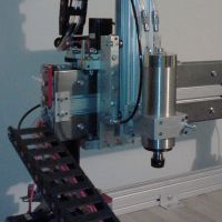
hotend installed and wired up, overall photo
CIMG1609.JPG
I think i'm ready for a initial power up test and firmware upload tomorrow.. hopefully everything here goes smooth....
Last edited by cambo3d on Sun Jun 16, 2013 4:08 pm, edited 4 times in total.
User avatar
Eaglezsoar
ULTIMATE 3D JEDI
Posts: 7159
Joined: Sun Apr 01, 2012 5:26 pm

Re: Another rostock max build

Post by Eaglezsoar »

cambo3d wrote:extruder done, wont be long now..My gears for the extruder were warped causing some binding. I had to do some sanding in order for it to spin freely. Very unusual. Seemed like the quality of those gears were lacking a bit but I got it to work. I didn't put a flat on the stepper motor shaft this time. Seemed like the press fit gear had plenty of bite to stay on the shaft.
final steps next, installing the hot end and finishing up the rest of the wiring. I should be able to power this thing up soon..
Thanks for the great pictures, they are going to be a great help when I get to those points in my build.
User avatar
cambo3d
ULTIMATE 3D JEDI
Posts: 1057
Joined: Thu Feb 07, 2013 10:03 pm
Location: Florida

Re: Another rostock max build

Post by cambo3d »

no problem, I wished more people posted there build logs on here. Because when I first started I was wondering whether I should buy this kit. Reading build logs from other people helps.

I still got a long ways to go, rostock max is finished but still have to do the calibration side of it and it doesn't look like its gonna be fun... after reading others post on here.

once I complete the build I plan on doing a complete review of the kit.
User avatar
foshon
Printmaster!
Posts: 600
Joined: Fri Mar 08, 2013 3:05 pm
Location: Just to the right of SeeMeCNC

Re: Another rostock max build

Post by foshon »

Very nice machine sir! I have used some of your ideas so far and I appreciate the time it took to post your build.
Purple = sarcasm

Please do a board search before posting your question, many have been answered with very time consuming detail already.
User avatar
cambo3d
ULTIMATE 3D JEDI
Posts: 1057
Joined: Thu Feb 07, 2013 10:03 pm
Location: Florida

Re: Another rostock max build

Post by cambo3d »

so here comes my first problem i cant get my lcd to display properly.

I've tried arduino 22 and 23, with marlin, then tried arduino 1.03 with repetier and the same happens on both firmwares. I've tried swapping the ribbon cables around, no joy.

I'm thinking my rambo is messed up or my lcd is messed up?

all i get is letters and boxes in marlin firmware
CIMG1613.JPG
in repetier firmware
CIMG1614.JPG
what am i doing wrong?

EDIT: PROBLEM FOUND http://forum.seemecnc.com/viewtopic.php ... &start=160
Last edited by cambo3d on Sun Mar 31, 2013 3:40 am, edited 1 time in total.
User avatar
cambo3d
ULTIMATE 3D JEDI
Posts: 1057
Joined: Thu Feb 07, 2013 10:03 pm
Location: Florida

Re: Another rostock max build

Post by cambo3d »

foshon wrote:Very nice machine sir! I have used some of your ideas so far and I appreciate the time it took to post your build.
thanks !
User avatar
foshon
Printmaster!
Posts: 600
Joined: Fri Mar 08, 2013 3:05 pm
Location: Just to the right of SeeMeCNC

Re: Another rostock max build

Post by foshon »

cambo3d wrote:so here comes my first problem i cant get my lcd to display properly.

I've tried arduino 22 and 23, with marlin, then tried arduino 1.03 with repetier and the same happens on both firmwares. I've tried swapping the ribbon cables around, no joy.

I'm thinking my rambo is messed up or my lcd is messed up?

all i get is letters and boxes in marlin firmware
CIMG1613.JPG
in repetier firmware
CIMG1614.JPG
what am i doing wrong?
Can't speak for Repetier, but the portion that is displaying in the marlin version is correct. It is showing your current temp / set point. I would lean toward connection issue as both screens have the same block pattern.
Purple = sarcasm

Please do a board search before posting your question, many have been answered with very time consuming detail already.
User avatar
cambo3d
ULTIMATE 3D JEDI
Posts: 1057
Joined: Thu Feb 07, 2013 10:03 pm
Location: Florida

Re: Another rostock max build

Post by cambo3d »

does anyone have working lcd firmware, either repetier or marlin that could try.
User avatar
mhackney
ULTIMATE 3D JEDI
Posts: 5391
Joined: Mon Mar 26, 2012 4:15 pm
Location: MA, USA
Contact:

Re: Another rostock max build

Post by mhackney »

Polygonhells's firmware worked for my LCD 1st time. I had to build my own harness so it was even more amazing the thing worked first time! I'd never got Marlin to work with RAMBo but use it with my H-1s and LCD displays.

Sublime Layers - my blog on Musings and Experiments in 3D Printing Technology and Art

Start Here:
A Strategy for Successful (and Great) Prints

Strategies for Resolving Print Artifacts

The Eclectic Angler
User avatar
cambo3d
ULTIMATE 3D JEDI
Posts: 1057
Joined: Thu Feb 07, 2013 10:03 pm
Location: Florida

Re: Another rostock max build

Post by cambo3d »

mhackney wrote:Polygonhells's firmware worked for my LCD 1st time. I had to build my own harness so it was even more amazing the thing worked first time! I'd never got Marlin to work with RAMBo but use it with my H-1s and LCD displays.
I've tried that firmware and still shows up the same way as marlin. Is there anything I need to do to arduino 1.03 before uploading it to the rambo? Or did you have to do anything to arduino 1.03?
User avatar
mhackney
ULTIMATE 3D JEDI
Posts: 5391
Joined: Mon Mar 26, 2012 4:15 pm
Location: MA, USA
Contact:

Re: Another rostock max build

Post by mhackney »

Nope, it just worked. It is odd that it shows a 2 x 8 matrix correctly in the upper left corner of the display. There are actually directives in both firmwares to specify the matrix dimensions. Double check those. If that is correct, then I suspect the connector cable first and if that verifies Ok, the LCD might be a problem.

Sublime Layers - my blog on Musings and Experiments in 3D Printing Technology and Art

Start Here:
A Strategy for Successful (and Great) Prints

Strategies for Resolving Print Artifacts

The Eclectic Angler
User avatar
cambo3d
ULTIMATE 3D JEDI
Posts: 1057
Joined: Thu Feb 07, 2013 10:03 pm
Location: Florida

Re: Another rostock max build

Post by cambo3d »

I just checked my ribbon cable, pin for pin, and they all have continuity. sigh.
User avatar
mhackney
ULTIMATE 3D JEDI
Posts: 5391
Joined: Mon Mar 26, 2012 4:15 pm
Location: MA, USA
Contact:

Re: Another rostock max build

Post by mhackney »

Go over the LCD board with a magnifier and look for loose/broken joints. I have 4 of these and they have been very reliable. Not to say a bad one might not squeak through though.

Since you seem to be getting partial display - and maybe enough to read the hotend temp, why not test that to see if the display works at least for that. Also, what happens when you use the selector knob to navigate the menus?

Sublime Layers - my blog on Musings and Experiments in 3D Printing Technology and Art

Start Here:
A Strategy for Successful (and Great) Prints

Strategies for Resolving Print Artifacts

The Eclectic Angler
User avatar
cambo3d
ULTIMATE 3D JEDI
Posts: 1057
Joined: Thu Feb 07, 2013 10:03 pm
Location: Florida

Re: Another rostock max build

Post by cambo3d »

selector knob seems to work but display only shows those two lines, sometimes random characters, sometimes just two lines of white boxes across the display.

I can scroll up and down in those two lines, I can change feedrate using the knob, I push on the knob and it beeps.

the temperature that it displays seem to change when i change the temperature.

I have looked over the back of the board, I see no obvious problems


and on a side note while trying to take the lcd back out, i broke the angle mounts for it. It didn't help that used wood glue to help hold the mount together. sigh.
User avatar
MorbidSlowBurn
Printmaster!
Posts: 169
Joined: Sun Mar 03, 2013 5:33 pm

Re: Another rostock max build

Post by MorbidSlowBurn »

I know you did a ring out on the pins but did you check to make sure adjacent pins weren't shorted. Don't think that will cause the issue but never know.
User avatar
cambo3d
ULTIMATE 3D JEDI
Posts: 1057
Joined: Thu Feb 07, 2013 10:03 pm
Location: Florida

Re: Another rostock max build

Post by cambo3d »

I'm sending my lcd back to seemecnc for replacement.

but in the meantime. I wanted to take some temperature readings with my thermocouple meter.

here are the results. what do you guys think of this? what are your opinions?
tempreading photo.jpg
the average temperature is the difference between the aluminum and brass parts of the nozzle.
From this chart it doesn't look like i'll be able to get the brass nozzle to 230, because aluminum temp always being higher and without damaging the peek.


on another note:
this bed rocks at 24v it heated up to 110. in a matter of minutes. Next to do test is to see how much current is exactly being drawn at 24v at the various temps on the heat bed
Last edited by cambo3d on Sat Mar 23, 2013 2:17 pm, edited 7 times in total.
User avatar
mhackney
ULTIMATE 3D JEDI
Posts: 5391
Joined: Mon Mar 26, 2012 4:15 pm
Location: MA, USA
Contact:

Re: Another rostock max build

Post by mhackney »

cambo3D, nice work. Looking at the heated bed section at the top, it shows that the reading the thermistor is sending to the controller is being held within a 1/2 degree C for all but the 61°C case - pretty nice control.

Measuring temp accurately with a thermocouple is a challenge. Did you insulate over the top of the thermocouple probe for instance?

A better way to check the thermistor against a thermocouple is to use boiling water - 100°C. If you stick the thermocouple and thermistor in the same pan of boiling water (careful of shorts if its a metal pan) they should both read 100°C. You can also use higher temperature fluids like silicone oil, etc to check calibration at higher temps. With this info, you can then calibrate your thermistor - given the thermocouple reading is accurate.

Sublime Layers - my blog on Musings and Experiments in 3D Printing Technology and Art

Start Here:
A Strategy for Successful (and Great) Prints

Strategies for Resolving Print Artifacts

The Eclectic Angler
User avatar
foshon
Printmaster!
Posts: 600
Joined: Fri Mar 08, 2013 3:05 pm
Location: Just to the right of SeeMeCNC

Re: Another rostock max build

Post by foshon »

cambo3d wrote:I'm sending my lcd back to seemecnc for replacement.

but in the meantime. I wanted to take some temperature readings with my thermocouple meter.

here are the results. what do you guys think of this? what are your opinions?
tempreading photo.jpg
the average temperature is the difference between the aluminum and brass parts of the nozzle.

Does the Aluminum temp at nozzle end is the bottom, top, or outside of the ring. I find it alarming to see the difference in those two measurments increase so much as temperature rises. Tells me either the thermocouple is having difficulty measuring the right temp or something is slowing hte transfer of heat between the alum and brass. How long did you let it soak for the measurments?
Purple = sarcasm

Please do a board search before posting your question, many have been answered with very time consuming detail already.
User avatar
cambo3d
ULTIMATE 3D JEDI
Posts: 1057
Joined: Thu Feb 07, 2013 10:03 pm
Location: Florida

Re: Another rostock max build

Post by cambo3d »

Does the Aluminum temp at nozzle end is the bottom, top, or outside of the ring. I find it alarming to see the difference in those two measurments increase so much as temperature rises. Tells me either the thermocouple is having difficulty measuring the right temp or something is slowing hte transfer of heat between the alum and brass. How long did you let it soak for the measurments?[/quote]


the measurement taken at the nozzle was inside the other thermistor hole.
User avatar
foshon
Printmaster!
Posts: 600
Joined: Fri Mar 08, 2013 3:05 pm
Location: Just to the right of SeeMeCNC

Re: Another rostock max build

Post by foshon »

cambo3d wrote:Does the Aluminum temp at nozzle end is the bottom, top, or outside of the ring. I find it alarming to see the difference in those two measurments increase so much as temperature rises. Tells me either the thermocouple is having difficulty measuring the right temp or something is slowing hte transfer of heat between the alum and brass. How long did you let it soak for the measurments?

the measurement taken at the nozzle was inside the other thermistor hole.
[/quote]


If you don't have plastic in there yet, pull out your tube and stick the probe right down the shaft to the tip. Let the nozzle soak at temp until it stabalizes.
Purple = sarcasm

Please do a board search before posting your question, many have been answered with very time consuming detail already.
User avatar
cambo3d
ULTIMATE 3D JEDI
Posts: 1057
Joined: Thu Feb 07, 2013 10:03 pm
Location: Florida

Re: Another rostock max build

Post by cambo3d »

will do, I didn't think about doing it that way. I'll try that and see if I get better brass readings. With the thermocouple in the brass nozzle, I should be able to get better measurements.
and i'll check my thermocouple as mhackney suggested.

edit: checked the thermocouple calibration against boiling water. It was just slightly off. 98.9 degrees Celsius so I adjusted it to 100. then rechecked.
will redo the test and post report.
User avatar
cambo3d
ULTIMATE 3D JEDI
Posts: 1057
Joined: Thu Feb 07, 2013 10:03 pm
Location: Florida

Re: Another rostock max build

Post by cambo3d »

So I redid the bed temperature test after some changes here is the result. Will redo the hotend temperature test. later tonight.
Edit: got side tracked and didn't get to the hotend test, will pick up again tomorrow.
heat bed temperature test 2.jpg
temperature graph, waited for the bed to reach room temp. rep host temp 24, thermocouple temp 24.5
Total actual time shown from room temperature to 115 degrees. Note: I am using a dedicated 24v 750watt 31amp Meanwell power supply with ssr to control power to my onyx. rambo board is run off stock 12v power supply and using marlin firmware. (stock firmware with no changes)
heat bed temperature graph.jpg
I did another test with repetier firmware installed. Heat up to 115 took about the same amount of time. One thing different about repetier firmware (stock firmware with no changes) is that it did a better job of keeping the temperature steady. less temperature flux. graph shown below.
repetier firmware heat bed test2.jpg
Last edited by cambo3d on Sun Mar 24, 2013 12:10 pm, edited 2 times in total.
User avatar
foshon
Printmaster!
Posts: 600
Joined: Fri Mar 08, 2013 3:05 pm
Location: Just to the right of SeeMeCNC

Re: Another rostock max build

Post by foshon »

WOW!! 110 degrees in just over what 4 or 5 minutes?!?! Awesome, looks like that one is dead on.
Purple = sarcasm

Please do a board search before posting your question, many have been answered with very time consuming detail already.
User avatar
cambo3d
ULTIMATE 3D JEDI
Posts: 1057
Joined: Thu Feb 07, 2013 10:03 pm
Location: Florida

Re: Another rostock max build

Post by cambo3d »

I read another post that repetier firmware has faster heat up times. Although 4 minutes to 110 is pretty good for me, I might try it just to see the difference.

when i was troubleshooting my lcd issue, swapping firmwares around, I'd forgotten that marlin firmware was reinstalled.

this gives me a good baseline reading to determine what temperatures i need to set in the host software to get my bed to required temperatures.
for example: if I wanted a bed temp of 110, i would need to set the temp in host to 115 or so because actual bed temp of aluminum is a little lower.(with marlin firmware)
Last edited by cambo3d on Sun Mar 24, 2013 12:12 pm, edited 1 time in total.
User avatar
Eaglezsoar
ULTIMATE 3D JEDI
Posts: 7159
Joined: Sun Apr 01, 2012 5:26 pm

Re: Another rostock max build

Post by Eaglezsoar »

It is interestint to note that as I read through the various parts of the forum, I see that about three people are experiencing the same white boxes on the
LCD display as Cambo3D is seeing. What the relevance is I don't know but why are 3 people all seeing the same thing on their displays? I guess we will
know once someone who is experiencing the problem gets it working.
Carl
Post Reply

Return to “The Build Zone”