Got my box delivered today and have noted all parts, only 1 screw missing and can get it locally so not worth bothering with.
Just completed punching out and removing tape from all melamine pieces, noticed that the piece that goes under the Onyx is white whereas everything else on my kit is black... not sure if that was an oversight or if it will even be seen. All bags neatly packed and screws were in their own zip locks. Nice touch! I have used a black sharpie to mark every bag after cross checking them for easy identification during the build.
Very excited right now! Might even be up past my bedtime!
Attachments
The black melamine punched out and tape removed... sorry the light sucks.
Unboxing the parts bags and preparing to check against packing list
Keep them coming! I want to see just how different the build is with the V2. I know the manual is there, but a build/review always reveals the kinks. Hope everything goes smoothly!
Calling it a night on day 1. Got my box at 2:30ish in the afternoon, counted parts, punched out all the melamine pieces and built up to page 47 in the manual. Hot end is drying overnight with the RTV compound and the Onyx will be part of tomorrow's build. Waiting on my Kapton tape and some other supplies for the hot end quick disconnect, but I can continue on other parts while I wait. Will also take some better photos hopefully with my Nikon for comparison for you all. Good night for now!
Attachments
Planning on getting some wire loom for the power leads and where ever else I can pretty it up, just waiting to see how much will be needed once I start putting in the Rambo board and such.
Got through page 47 of the build with no problems so far... going to leave some for tomorrow!
Just another shot of the stacked Black melamine parts
cgbobio wrote:Got my box delivered today and have noted all parts, only 1 screw missing and can get it locally so not worth bothering with.
Just completed punching out and removing tape from all melamine pieces, noticed that the piece that goes under the Onyx is white whereas everything else on my kit is black... not sure if that was an oversight or if it will even be seen. All bags neatly packed and screws were in their own zip locks. Nice touch! I have used a black sharpie to mark every bag after cross checking them for easy identification during the build.
Very excited right now! Might even be up past my bedtime!
There was another user who got a V2 kit in black and he complained about the white part that goes under the Onyx and yes, it can be seen. You may want to put a couple of
coats of high temperature black paint on that part. The part is not made in black on any kit.
Still waiting for my Kapton Tape for the Onyx bed so I skipped that part for now and continued on with the build of my V2.
I found a few areas in the manual that had me scratching my head because screws or something didn't match what was called for...
I'll try and point those parts out in the following photos.
Attachments
When threading the wires through the alluminum extrusions, I found it worked best to turn the alluminum in the opposite direction with one hand while feeding the wires with the other hand... this made the wires pull themselves through much easier.
Front of the printer showing the X and Y motor positions
This is the "X" axis motor from the front left of the printer
This is the "Z" axis motor and power supply from the back of the printer
This is the "Y" axis motor From the front right of the printer
Ok so now I see that my images are posting in reverse order so I will try and post them to show the order that the build progressed today...
Attachments
This step called for a #4 3/8" Pan Head Phillips Machine Screw. The baggie labeled here holds the screws I think were meant to be used... I labeled all the baggies when I first received the kit and never came across the size mentioned in the documentation.
Very important part of the build here... you need to take the inside and outside pieces of the cheapskate and match them up before screwing anything to them... the holes are cut so that they only fit one way!!! In the image you can see that to the left of the eyes, the holes are farther apart and to the right of the eyes they are closer. Make note of that when you are assembling the inside cheapskate panel or the holes will not line up when you put the two halves together!
These holes are awfully close to edge and just press fitting the t-nuts caused a little concern. Going to have to break out the black sharpie!
I found it much easier to route the wires (especially the 18 gauge) through the alluminum extensions by removing the idler bearing under the mount and then replacing it once the wires were through.
replacing the idler bearing once the wires were pulled through.
The wires successfully pulled through the alluminum and routed out the bottom of the mount.
This is the "new" upper tower mount that was different than the image on page 71 of the documentation. Caused some concern at first, thought I had not been sent any of these until I matched up the remaining pieces I had with the hole patterns on the documentation image.
The assembled top section. I wound up reversing the large plate and had to invert all the upper tower mounts once I saw my mistake.
End of Day 2, I could have kept going, but I wanted something to do this weekend!
Not sure if this was taken care of in v2, but in V1, I think there is an issue with running the endstop wires down the same extrusion as the stepper motor wires. Not sure if this is what is done here... but might want to take heed.
the endstop wires will take interference from the stepper motors.
Though, this is recall.... anybody know If I am correct?
neurascenic wrote:Not sure if this was taken care of in v2, but in V1, I think there is an issue with running the endstop wires down the same extrusion as the stepper motor wires. Not sure if this is what is done here... but might want to take heed.
the endstop wires will take interference from the stepper motors.
Though, this is recall.... anybody know If I am correct?
BTW, nice looking so far!
Thanks for the heads up! The wires in this build have all the end stops in the X axis, the 18 gauge (for stepper motors ?) is in the Z axis by itself and the 22 and 26 gauge wires (for the hot end) are in the Y axis extrusion. I'm hoping this solved the issues you are speaking of.
Thanks for the compliments, I'm having a blast assembling this thing!
Yes that should take care of the issue, you dont want the end stop wires running with any other wires in such a confined space as it has a problem with picking up the noise from the other wires and you would never get your machine right.
If the end stops are all run by themselves down one extrusion you should be all set!
By no means the final build, I have a bunch of soldering, crimping and wire management to do today, but her is where I am at right now. Got the belts run as well, so just a few more items and. I will be uploading the firmware and starting the calibration soon.
Attachments
Put the smoked plexi in, but still have to fi nish up wiring. I will post better images later tonight when I finish for the day.
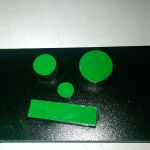
Just finishing up the quick disconnects and wiring up the Rambo. Found a few more issues with the documentation where it explains the connections for the end stops... The image shows a green rectangle for the end stops to be plugged into, but on page 164, the same wires are plugged into the min connectors instead of the max connectors... Any ideas? I am assuming that we want the max input for the endstops not the min. Too late to take photos tonight so I will try and post some more tomorrow of the almost complete build.
cgbobio wrote:Just finishing up the quick disconnects and wiring up the Rambo. Found a few more issues with the documentation where it explains the connections for the end stops... The image shows a green rectangle for the end stops to be plugged into, but on page 164, the same wires are plugged into the min connectors instead of the max connectors... Any ideas? I am assuming that we want the max input for the endstops not the min. Too late to take photos tonight so I will try and post some more tomorrow of the almost complete build.
You are correct, the endstops are supposed to plug into the Max connectors. The image on Page 164 is in error.
Thanks for the help Eaglezsoar. Looks like all I have left is wiring up the quick releases on the hot end then loading the firmware/software. Still waiting on my filament to arrive so for now, I'll just be watching the 3D printer ballet! I will try and get some better final build pictures today.
So I'm guessing that the peek and layer fans are going to require an additional printed shroud since it seems I have no parts left in my bags?
cgbobio wrote:
So I'm guessing that the peek and layer fans are going to require an additional printed shroud since it seems I have no parts left in my bags?
Yeah you will have to print those parts , kinda the final step to finishing the build. You can stick your peek fan in untill you make the shroud for it.
Cheers Prozac! All I have left now is to pick up the crimping connectors for the hot end, solder it up and I will be done with the build! Still need to load software, but the assembly will be complete... Except for upgrades of course! More photos later today.
Out of box build complete! Now for the upgrades!
Here are some pictures of the Black V2 for all of you that wanted to see one built. The only thing I did different was add the disconnect on the hotend, everything else was stock according to the manual.
Attachments
The upper part of the tower with black frosted lexan on the corners
Outside face with SeeMeCNC eyes cut into the melamine
The cheapskate
Closeup of the hotend and the hotend assembly
The hotend looking down at the Oynx plate
Laser cut SeeMeCNC logo on the top panels
The new upper tower mount and black frosted lexan panels on the top cap
The EZStruder installed
Side panels the screw on with nylon thumb screws
Back of the printer with Z axis tower and power cord
OK, so I'm getting ready to download software and firmware etc to load up my new V2, I do a test power on to make sure the Rambo fan is powing up and I get this screen... Does this mean it is already loaded and should I reload it?
Attachments
LCD display on test power on before loading any software