Aluminum is actually more conductive than "steel" (I'm including almost all alloys of steel). There are alloys of Al that are less than alloys of steel - it all depends on what's being used. You can get a 12" square of 1/8" 3003 aluminum for about $12. How cheap does it need to be? It may be more pricy for him since he is in the laser business for steel and not set up for aluminum.
1. The max is about 12 1/8" (Onyx) diameter.
2. just thermal conductivity and flex depending on gauge
How much is he talking about for a steel disk?
Also, keep flatness in mind. These thin sheets of steel and aluminum are not guaranteed to be flat and may well have a bow in them. Look at my Heat Dissipator fiasco for more information. My advice would be 1/4" MIC-6 aluminum. However, you will need more power to your heated bed or wait a long time to get up to temperature.
PEI print bed surface experiments
Re: PEI print bed surface experiments
Sublime Layers - my blog on Musings and Experiments in 3D Printing Technology and Art
Start Here:
A Strategy for Successful (and Great) Prints
Strategies for Resolving Print Artifacts
The Eclectic Angler
-
Eaglezsoar

- ULTIMATE 3D JEDI
- Posts: 7185
- Joined: Sun Apr 01, 2012 5:26 pm
Re: PEI print bed surface experiments
Thanks for correcting me Michael. I thought the heat transmission would be higher with steel, live and learn. On a different subject when you get a chance to play with themhackney wrote:Aluminum is actually more conductive than "steel" (I'm including almost all alloys of steel). There are alloys of Al that are less than alloys of steel - it all depends on what's being used. You can get a 12" square of 1/8" 3003 aluminum for about $12. How cheap does it need to be? It may be more pricy for him since he is in the laser business for steel and not set up for aluminum.
1. The max is about 12 1/8" (Onyx) diameter.
2. just thermal conductivity and flex depending on gauge
How much is he talking about for a steel disk?
Also, keep flatness in mind. These thin sheets of steel and aluminum are not guaranteed to be flat and may well have a bow in them. Look at my Heat Dissipator fiasco for more information. My advice would be 1/4" MIC-6 aluminum. However, you will need more power to your heated bed or wait a long time to get up to temperature.
MatterHackers software I would be interested in your opinion. Just call me thread buster.
Re: PEI print bed surface experiments
Mike,
tx.
i'm getting quotes on stainless and aluminum, in around 1/8" and 1/4" discs. will probably just burnish the edges slightly to prevent cuts..
per my guy, the consistency on thickness (from one side to another on an average 12" disc) should only be .001-.003"
he cuts steel & alum daily (they have 4 large laser sets and a full steel shop as well-it's a $50M+ operation), so the real cost is the hassle factor on a tiny order like this......
on a side note -- i'm wondering if alum isn't going to be actually a BETTER thermal transmitter than the borosilicate glass sheet....
Re: PEI print bed surface experiments
Thickness consistency is not really the issue. The issue is not THICKNESS consistency, it's FLATNESS. Please read my posts on aluminum heat dissipators. Of course Al is a better thermal transmitter than glass, MUCH better! I manufactured a heat dissipator for the Rostock Max last year solely for the purpose of evening out the temp gradient on the bed/glass. Trust me when I tell you, unless you are purchasing material that is precision ground to be FLAT you are taking a risk that the plate will be unusable. I have 25 Al plates here in my shop to prove that. The laser cutting process also puts in a lot of thermal stress, which can show up as a warped part in thinner materials. If you go down this path, tell your guy that the product has to be flat to within +/- .01mm or it is not going to work and get it in writing. If you were putting glass on top of it, it wouldn't be a big issue since the glass is very flat. But the PEI will conform to the metal and you'll not be able to level your bed for love or money.
Sublime Layers - my blog on Musings and Experiments in 3D Printing Technology and Art
Start Here:
A Strategy for Successful (and Great) Prints
Strategies for Resolving Print Artifacts
The Eclectic Angler
Re: PEI print bed surface experiments
so i got curious and looked this up....
borosilicate glass has a thermal conductivity of 1.1-1.35 W/m-K... That's pretty awefully slow.
BUT it does mean that the glass doesn't fluctuate AS MUCH.....
stainless steel comes in at around 16.2-17.5 W/m-K (depending on temp differentials, etc)
aluminum - 205 - 225 W/m-K
This makes me wonder if going with a thick aluminum plate might actually be more problematic, because it could allow for massive/rapid cooling???
thoughts?
I've got some quotes on 1/8" discs (laser cut and sanded edges) - around $18 for alum 5052 and just over $25 for stainless 304
am probably going to harass him for a 1/4" size as well, to see if he can do that..
Overall, i'm thinking this (PEI adhered to an alum plate) will actually be way less expensive (and probably a lot easier) than the glass.....
Re: PEI print bed surface experiments
mhackney wrote:Thickness consistency is not really the issue. The issue is not THICKNESS consistency, it's FLATNESS. Please read my posts on aluminum heat dissipators. Of course Al is a better thermal transmitter than glass, MUCH better! I manufactured a heat dissipator for the Rostock Max last year solely for the purpose of evening out the temp gradient on the bed/glass. Trust me when I tell you, unless you are purchasing material that is precision ground to be FLAT you are taking a risk that the plate will be unusable. I have 25 Al plates here in my shop to prove that. The laser cutting process also puts in a lot of thermal stress, which can show up as a warped part in thinner materials. If you go down this path, tell your guy that the product has to be flat to within +/- .01mm or it is not going to work and get it in writing. If you were putting glass on top of it, it wouldn't be a big issue since the glass is very flat. But the PEI will conform to the metal and you'll not be able to level your bed for love or money.
yes, i discussed this with him.. this might be a challenge, if it's got to be within that tolerance level (<.0005") - -although I'm a bit unsure why a .02 mm variance is going to kill you....
I'm operating under the theory that ALL bed material (glass included) is not flat. I measure out and mark my glass, so it's aligned to the same rotational orientation every time, so after I've leveled out the unit, as long as I replace it exactly the same way, it'll be consistent.
If exact tolerances really are the issue, you should be doing this anyway, because you're not going to find much in the way of metal that's consistent better than .03, without paying 10-20x the price.
Re: PEI print bed surface experiments
.02mm difference across the build surface can have an effect on whether a large part will get guid first layer adherence. You could loosen it up a bit to +/- .025mm, I was being a bit conservative.
There is "flat" and there is "flat". Glass is remarkably flat and well within the tolerance we need. But, it can bend/warp and that has caused folks some problems with large thin plates on PCB heaters.
There is "flat" and there is "flat". Glass is remarkably flat and well within the tolerance we need. But, it can bend/warp and that has caused folks some problems with large thin plates on PCB heaters.
Sublime Layers - my blog on Musings and Experiments in 3D Printing Technology and Art
Start Here:
A Strategy for Successful (and Great) Prints
Strategies for Resolving Print Artifacts
The Eclectic Angler
Re: PEI print bed surface experiments
I'm not ignoring your question on MatterControl Eagle! Just thinking about what to say. It might be a few days.
Sublime Layers - my blog on Musings and Experiments in 3D Printing Technology and Art
Start Here:
A Strategy for Successful (and Great) Prints
Strategies for Resolving Print Artifacts
The Eclectic Angler
Re: PEI print bed surface experiments
mhackney wrote:.02mm difference across the build surface can have an effect on whether a large part will get guid first layer adherence. You could loosen it up a bit to +/- .025mm, I was being a bit conservative.
There is "flat" and there is "flat". Glass is remarkably flat and well within the tolerance we need. But, it can bend/warp and that has caused folks some problems with large thin plates on PCB heaters.
Agreed.. .025mm (which is .001") is right about normal tolerance on this material, from what I'm told.
That said, if you're putting down >.2 mm layers (I put first layer at .35mm) and have the bed hot enough and your extrusion slow enough, first layer adhesion should NOT to be a major issue.
I did have issues early on, but am currently running Kapton tape, Aqua Net unscented hairspray, and laying the first layer at 100c.. My biggest issue is that i often have to pry them off the tape with a paint scraper!
I suppose this brings us to the question of what is expected tolerance and application for 3d printing.
I'm doing nothing but prototyping, 90% of which is for mechanical/concept proofing, and only 10% for visual.. so i'm not hung up on a .3mm variance. My mindset has always been that this process is not without a bit of a "fudge factor", because it's running a lot of moving mechanical parts which were mass produced with sloppy tolerances.. So to expect a guaranteed <.01 mm perfect product seems (to me anyway) to be a bit out of the picture....
thoughts?
Out of the box, my heat bed has more than a .5mm concave center. annoying. but not earth-shattering.. I have to remind myself that I've replaced a $350,000 SLA machine with a $1400 desktop printer which runs at about 4% of the operating cost....
Now if my Full Spectrum SLA system will just get here this week......
-
Eaglezsoar
- ULTIMATE 3D JEDI
- Posts: 7185
- Joined: Sun Apr 01, 2012 5:26 pm
Re: PEI print bed surface experiments
Could you give us a quick blurb on how you got it on the tape with a minimum of bubbles?
That, to me, is the hardest part with dealing with this stuff. I tried Silicone caulking as Michael
did and it was a disaster. I have the 1" tape but I am afraid of making a mess.
That, to me, is the hardest part with dealing with this stuff. I tried Silicone caulking as Michael
did and it was a disaster. I have the 1" tape but I am afraid of making a mess.
Re: PEI print bed surface experiments
Eagle, how was the silicone a disaster?
Sublime Layers - my blog on Musings and Experiments in 3D Printing Technology and Art
Start Here:
A Strategy for Successful (and Great) Prints
Strategies for Resolving Print Artifacts
The Eclectic Angler
-
Eaglezsoar
- ULTIMATE 3D JEDI
- Posts: 7185
- Joined: Sun Apr 01, 2012 5:26 pm
Re: PEI print bed surface experiments
I used a different type of RTV clear silicone smoothed it out really nice and waited about 36 hoursmhackney wrote:Eagle, how was the silicone a disaster?
and noticed the the center of the PEI was domed a little. After scratching my head awhile I decided
to pull off the PEI and found the the silicone in the center never cured. I threw the stuff in the trash
cursed and bought some 1" 3M 468 tape. When I get up the nerve I will try the tape but after using
the self adhesive PEI and not being able to push out the bubbles I am a little gun shy.
Re: PEI print bed surface experiments
I guess the silicone in the center was like silicone in a tube! You can accelerate the curing with heat. Also, weighting/pressing the PEI and glass to keep it flat during curing is necessary - but you may have done that. I would recommend trying it again with silicone and maybe waiting 2 days, then move to your printer and heat to 90°C for an hour or two. It really does work nicely to hold the PEI. I've seen no delaminations or other issues.
Sublime Layers - my blog on Musings and Experiments in 3D Printing Technology and Art
Start Here:
A Strategy for Successful (and Great) Prints
Strategies for Resolving Print Artifacts
The Eclectic Angler
-
Eaglezsoar
- ULTIMATE 3D JEDI
- Posts: 7185
- Joined: Sun Apr 01, 2012 5:26 pm
Re: PEI print bed surface experiments
Very good ideas, thank you for passing them on. I would rather use the silicone, the tape is the stickiest stuff I have ever seen.mhackney wrote:I guess the silicone in the center was like silicone in a tube! You can accelerate the curing with heat. Also, weighting/pressing the PEI and glass to keep it flat during curing is necessary - but you may have done that. I would recommend trying it again with silicone and maybe waiting 2 days, then move to your printer and heat to 90°C for an hour or two. It really does work nicely to hold the PEI. I've seen no delaminations or other issues.
I did have the weight on the silicone but did not try the cure with heat. Will try again.
Re: PEI print bed surface experiments
And let it cure for an extra day just to be sure.
Sublime Layers - my blog on Musings and Experiments in 3D Printing Technology and Art
Start Here:
A Strategy for Successful (and Great) Prints
Strategies for Resolving Print Artifacts
The Eclectic Angler
-
Eaglezsoar
- ULTIMATE 3D JEDI
- Posts: 7185
- Joined: Sun Apr 01, 2012 5:26 pm
Re: PEI print bed surface experiments
Will do and thank you, it will be a little while because the problem with me that you are aware ofmhackney wrote:And let it cure for an extra day just to be sure.
has, in the past three or four days, has changed from a 3 to an 8 or so but doesn't keep my big
mouth from typing on the forums. No acknowledgement is necessary.
Re: PEI print bed surface experiments
my method for the tape was to leave the backing on until all the tape was successfully placed on the glass. Application of the tape was typical method by attaching the cut end with a little overhang onto the glass, and pulling the roll out just past the other end of the glass, slowly pressing the tape to the glass from the cut end until the entire length was in place. then i cut the strip off the roll and repeated. bubbles with this .5" tape didn't seem to be a problem to push out once it was on the glass, you just want to avoid folds. also when laying down the tape it is better to have a small gap between the lengths vs. overlap. I used the same method with the PEI, i started in one corner holding the other end fist high above the table i was working on, and slowly pressed it into the tape while working out any bubbles.Eaglezsoar wrote:Could you give us a quick blurb on how you got it on the tape with a minimum of bubbles?
That, to me, is the hardest part with dealing with this stuff. I tried Silicone caulking as Michael
did and it was a disaster. I have the 1" tape but I am afraid of making a mess.
I will cut this today and print on it, hopefully it will work
-
Eaglezsoar
- ULTIMATE 3D JEDI
- Posts: 7185
- Joined: Sun Apr 01, 2012 5:26 pm
Re: PEI print bed surface experiments
Hopefully it will work and I want to thank you for the tips.
When I can move better I want to try one attempt with the silicone again
then use the tape on my two Rmax printers. I was working on the Orion first.
When I can move better I want to try one attempt with the silicone again
then use the tape on my two Rmax printers. I was working on the Orion first.
Re: PEI print bed surface experiments
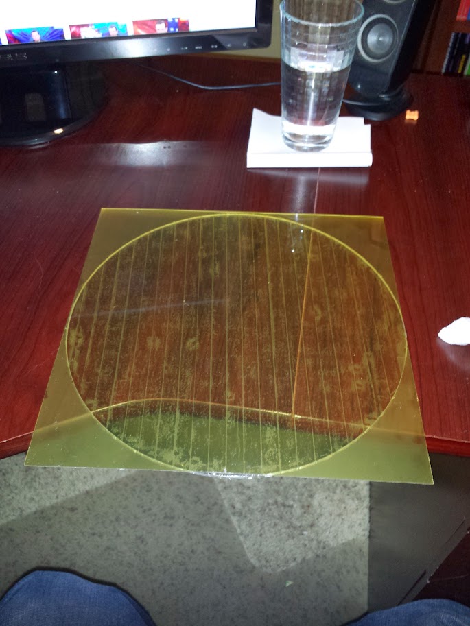
Just got my PEI and 3M tape in today.... I got a couple sheets of the .03" PEI - will see how that works.
Tried playing around with it a bit, even printed directly on it (clipped to the heat table directly)..
1. it's tremendously faster on temp ramp-up without the glass -- obviously due to the much higher thermal conductivity of PEI than that of borosilicate glass.
2. it leaves a significantly beautiful finish on parts.. I'm printing PLA mainly (for strength), and the finish is really impressive. I ran into a few issues because the .03" is quite flimsy and curls tremendously when heated. I'm going with the matte side, as it leaves a very professional looking finish.
I am going to be interested in how well it turns out when bonded to glass-i'm mounting one sheet on my glass, and have it curing under a 180lb load of batteries today/tonight. It will probably be ready to print in the morning, so we'll see...
-
Generic Default

- Printmaster!
- Posts: 558
- Joined: Mon Jun 03, 2013 6:56 pm
- Contact:
Re: PEI print bed surface experiments
PEI has a much lower thermal conductivity than any glass or any metal. If you touch it, it won't burn you immediately. It your fan blows on it, it won't cool down quickly. When your plastic gets extruded onto it, it won't cool down quickly. It's not very dense and it doesn't have a lot of thermal capacity, so it heats up quickly. I think the mass production of 3D printers over the next few years will mean that thousands of 2-year-olds will be burning their fingers on inadequately designed 3d printers, both hotends and beds. PEI is a good solution to make printers just a *little bit safer for the 7 billion of us who didn't build their own robot.
So I think it's best to have a build plate with a rigid, warp resistant flat plate of metal (mic-6 maybe) covered with a thin sheet or film of PEI plastic.
A Stratasys machine I used a few times has replaceable injection molded plates made out of some kind of high temperature glass-filled black plastic (probably PPA). The rough surface of the glass filled plastic makes printed parts stick until they're pryed off. Of course they don't have to worry about bed temperature because the entire build chamber is heated (and patent monopolized too). Glass filled makes everything stronger and more rigid, of course we will need to get a suitable bed material for printing higher temperature plastics, but we have a few years months to do that.
I know you guys mostly use PLA and some of you use ABS, but we need a solution that works for everything. What will happen when we try printing a plastic with a higher melting point than PEI? Nylon, polycarbonate, PPA, FEP, PAI, PEI, and all of the other ones I will [hopefully] be extruding this year might damage the PEI sheet on the plate when printing.
You guys who bought PEI to test as a bed material need to push it to its limits so that everyone who reads technical stuff like this thread can evaluate it. I'm convinced that it's a great choice for PLA, but that's about it for now.
Check out the Tri hotend!
-
neurascenic
- Printmaster!
- Posts: 217
- Joined: Fri Nov 15, 2013 10:05 pm
- Location: Denver Colorado
- Contact:
Re: PEI print bed surface experiments
Generic Default wrote: I know you guys mostly use PLA and some of you use ABS, but we need a solution that works for everything. What will happen when we try printing a plastic with a higher melting point than PEI? Nylon, polycarbonate, PPA, FEP, PAI, PEI, and all of the other ones I will [hopefully] be extruding this year might damage the PEI sheet on the plate when printing.
.
slab of Granite or other polished stone. it would take a little while to heat up if thick as it has a high thermal mass, but it doesn't give up it's heat like metal does.
I am a fool entrapped within my own wisdom.
Re: PEI print bed surface experiments
It's a GREAT choice for PLA, ABS and polycarbonate. I've run enough prints of all three of these to be comfortable with it. I think a "universal print surface" for all materials is a Holy Grail and might be an unrealistic expectation. Nylon in particular is persnickety. I haven't tried Ninjaflex on the PEI yet but I would wager it will work fine too.
Sublime Layers - my blog on Musings and Experiments in 3D Printing Technology and Art
Start Here:
A Strategy for Successful (and Great) Prints
Strategies for Resolving Print Artifacts
The Eclectic Angler
Re: PEI print bed surface experiments
After a few hours of printing on my new assembly, I'm in agreement..mhackney wrote:It's a GREAT choice for PLA, ABS and polycarbonate. I've run enough prints of all three of these to be comfortable with it. I think a "universal print surface" for all materials is a Holy Grail and might be an unrealistic expectation. Nylon in particular is persnickety. I haven't tried Ninjaflex on the PEI yet but I would wager it will work fine too.
PLA:
I did a couple towers (4mm diameter 22mm tall). perfect adhesion, no problems at all.
ABS - 2 conical assemblies. again perfect adhesion.
I'm running another set on PLA at the moment, may snap some photos, as these parts aren't 'classified'.....
This really has changed the game, in my opinion.
1. no more pulling the glass to clean and re-apply Kapton tape.
2. No more hair spray.
3. no more constant recalibration. just fire it up and print!
4. lower print temp is nice as well - i'm running 210/100 on first layer and 205/90 thereafter. This speeds up the ramp-up time by a few minutes...
I'm going to explore thinner PEI sheets on aluminum plates - in my opinion it'll be a lot faster temp ramp-up on the bed.
Does anybody see any issue with having a faster temp fluctuation (higher thermal conductivity) on the bed?
Re: PEI print bed surface experiments
I totally agree with the game changer comment. I've printed 100s of parts now and there are no mars, digits, burns on the PEI at all. It's in it for the long haul. And I love the crisp "snap" when parts come off.
Sublime Layers - my blog on Musings and Experiments in 3D Printing Technology and Art
Start Here:
A Strategy for Successful (and Great) Prints
Strategies for Resolving Print Artifacts
The Eclectic Angler