Page 1 of 2
Effects of microstepping and segmentation on print qualty
Posted: Thu Mar 30, 2017 10:03 am
by dc42
Delta printer users may be interested in the results of some testing I did to see what were the effects on print quality of changing microstepping and introducing segmentation. See
http://forums.reprap.org/read.php?178,759228 for the discussion.
Are there any Rostock users running the stock electronics and firmware who would like to try printing the test piece?
Re: Effects of microstepping and segmentation on print qualty
Posted: Thu Mar 30, 2017 11:02 am
by bruceg
Would be happy to, however my available nozzle sizes are 0.3, 0.5 & 0.6, so not sure if that would preclude my machine for your purposes given that your gcode file appears to be for a 0.4mm nozzle.
Re: Effects of microstepping and segmentation on print qualty
Posted: Thu Mar 30, 2017 3:01 pm
by dc42
bruceg wrote:Would be happy to, however my available nozzle sizes are 0.3, 0.5 & 0.6, so not sure if that would preclude my machine for your purposes given that your gcode file appears to be for a 0.4mm nozzle.
Would you like me to re-slice it for a different nozzle size, and if so, which one? Layer height is 0.2mm first layer and 0.1mm after that.
Re: Effects of microstepping and segmentation on print qualty
Posted: Thu Mar 30, 2017 3:27 pm
by bruceg
dc42 wrote:
Would you like me to re-slice it for a different nozzle size, and if so, which one? Layer height is 0.2mm first layer and 0.1mm after that.
0.3 please, that is what is mounted and i seem to be in a fiddly bits mode at the moment...
Re: Effects of microstepping and segmentation on print qualty
Posted: Thu Mar 30, 2017 5:06 pm
by borrillis
Count me in. I have an E3D mounted but it's still using the accelerometer probe and the rambo.
Re: Effects of microstepping and segmentation on print qualty
Posted: Fri Mar 31, 2017 12:09 am
by 626Pilot
Why did you use 0.5mm segments?
Re: Effects of microstepping and segmentation on print qualty
Posted: Fri Mar 31, 2017 2:48 am
by dc42
626Pilot wrote:Why did you use 0.5mm segments?
Because 100 segments/sec is a commonly used setting in firmwares that use segmentation, and I was printing at 50mm/sec.
Re: Effects of microstepping and segmentation on print qualty
Posted: Fri Mar 31, 2017 4:11 am
by dc42
bruceg wrote:dc42 wrote:
Would you like me to re-slice it for a different nozzle size, and if so, which one? Layer height is 0.2mm first layer and 0.1mm after that.
0.3 please, that is what is mounted and i seem to be in a fiddly bits mode at the moment...
I've re-sliced the file for a 0.3mm nozzle and saved it at
https://dl.dropboxusercontent.com/u/193 ... -0.3.gcode. Please edit the start of the file to set the temperatures you want, also remove the M0 command at the end if it isn't safe to turn the motors off on your printer at the end of a print.
Re: Effects of microstepping and segmentation on print qualty
Posted: Fri Mar 31, 2017 8:23 pm
by bruceg
dc42 wrote:
I've re-sliced the file...
Thank you, printing at the moment. I did need to change (Repetier 0.92.2 2016 12 27)
to
in order to get down to the bed =;D Suspect the G28 is not required but that is the order of go i have been using in blissful ignorance since getting the printer...
Re: Effects of microstepping and segmentation on print qualty
Posted: Sat Apr 01, 2017 10:03 pm
by bruceg
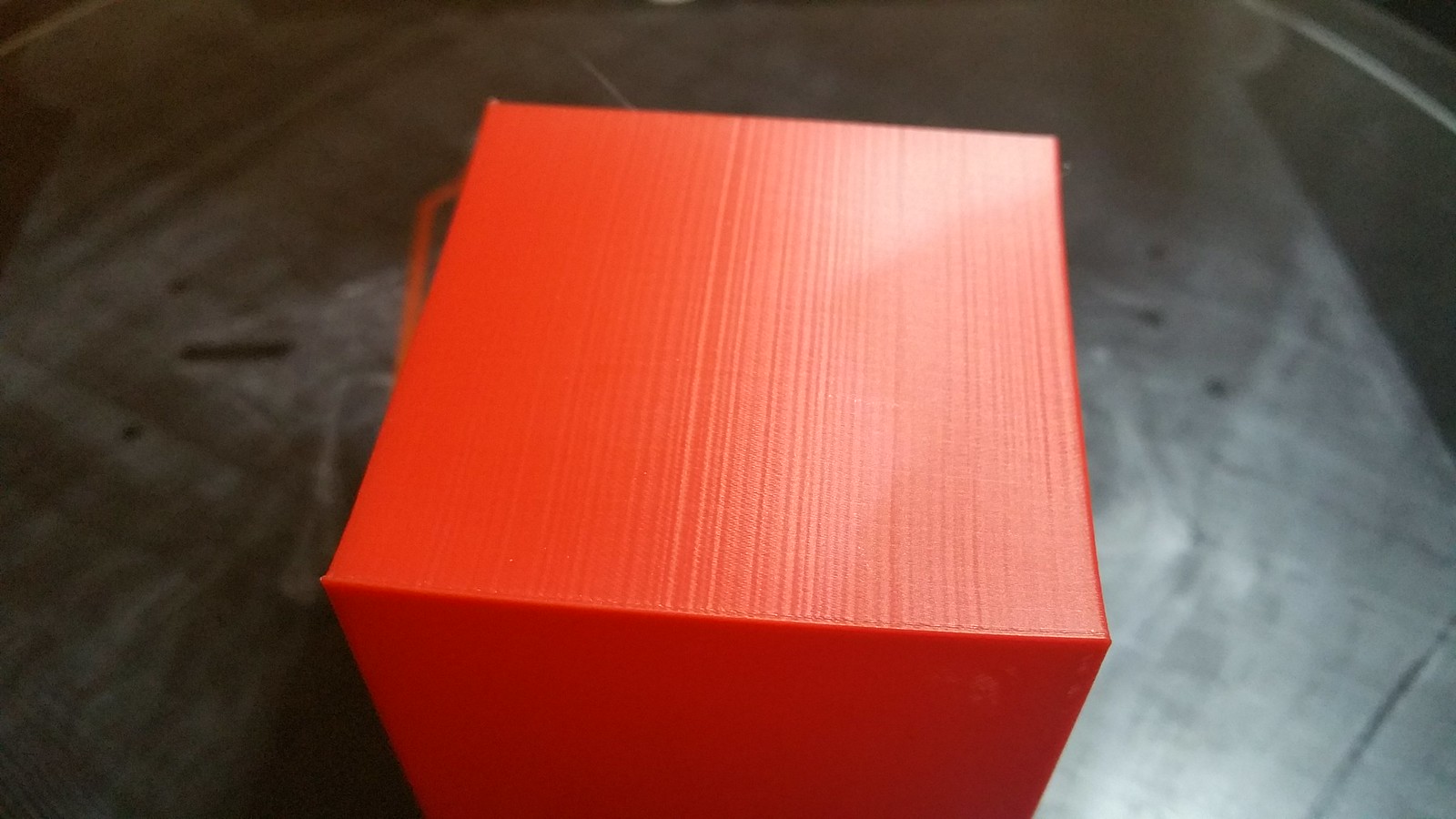
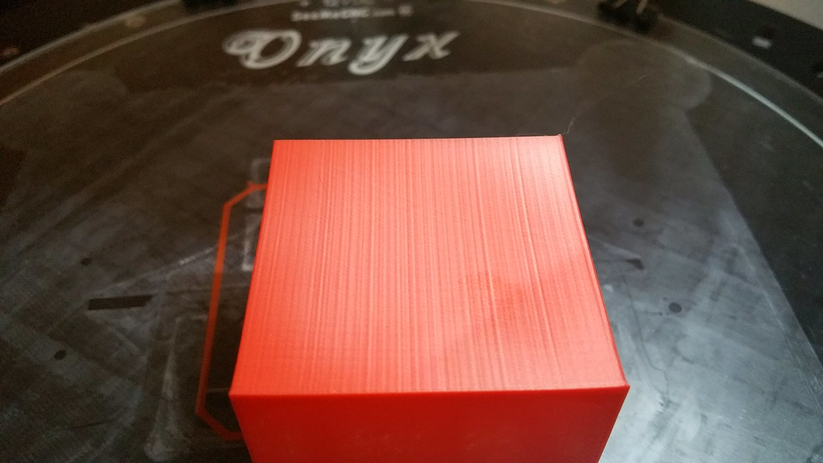
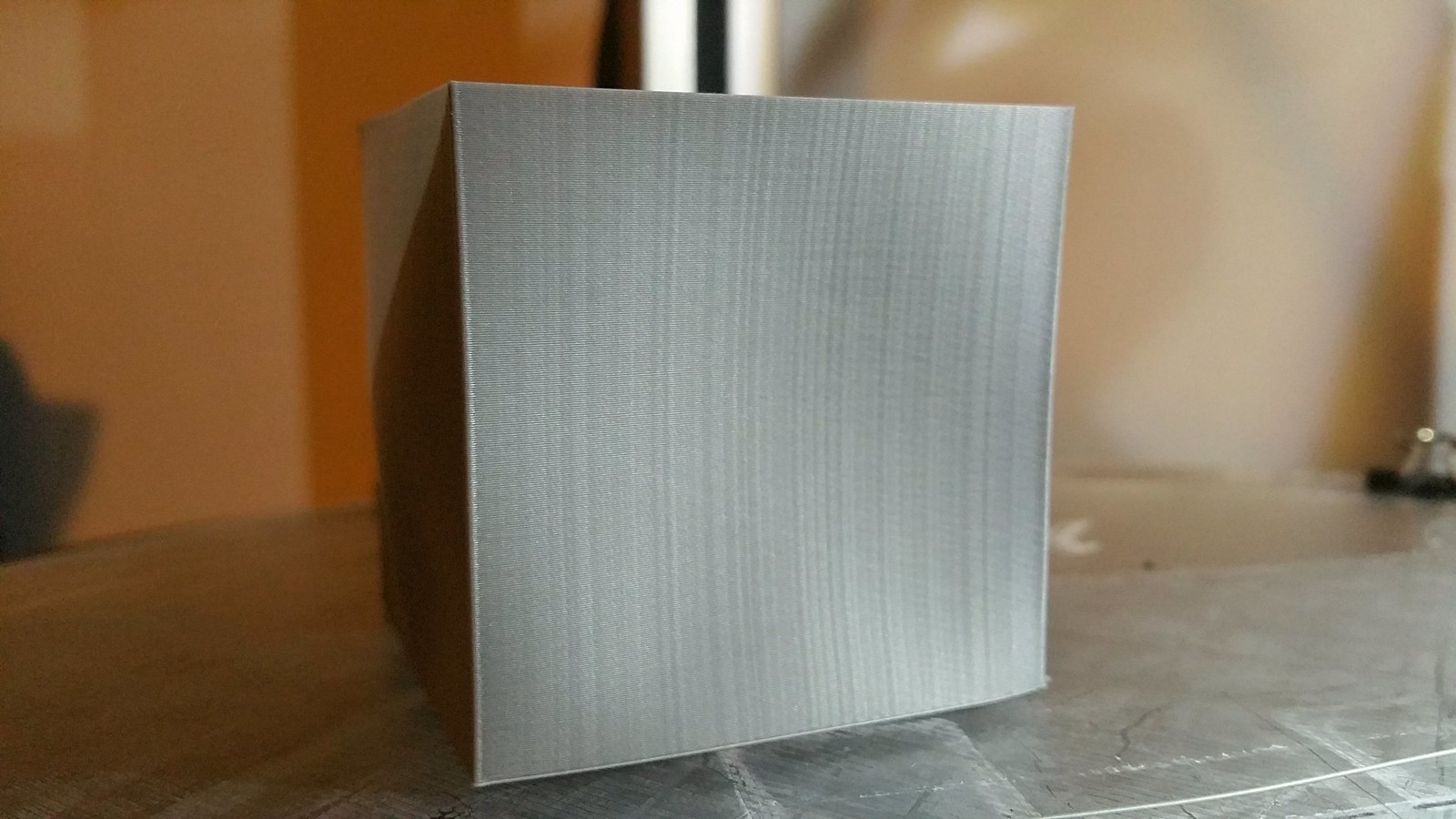
Well, not sure if the segmentation effects are apparent in the mechanical "noise" but here are a few images,
the rest here. There certainly are some interesting patterns. The notation in file names is as follows: X+> indicates side printed in positive X direction (from X-tower towards Y-tower), Y+> indicates side printed in positive Y direction (towards Z tower) with X-> and Y-> the opposite directions respectively. _1 denotes the left side of the face and _2 denotes the right.
Rambo + Repetier 0.92.2 (16x microstep), V2 Max (200 step/rev, extruder ~90step/mm) with ballcup arms, molded carriages, Prometheus set up after
ccavanaugh with 0.3mm nozzle, PLA. Only change to supplied gcode (50mm/s spiral) was reducing retraction on base layers to 1mm and swap of M83:G90 as indicated above.
Re: Effects of microstepping and segmentation on print qualty
Posted: Mon Apr 03, 2017 12:19 am
by nebbian
Hey Bruceg,
I've been investigating this a lot on the other thread, and might have found a way to isolate the stepper noise from the segments.
Try printing at 101% of the layer height you are already printing at. So if you print at 0.1mm, try printing with layer height of 0.101. If printing at 0.2, try 0.202 layer height.
You might then see a moire pattern, which is caused by the motor steppers. Vertical lines might be caused by segments.
I'd be interested to see your results.
Re: Effects of microstepping and segmentation on print qualty
Posted: Wed Apr 05, 2017 7:35 pm
by 0110-m-p
I'll play. I've always had a light amount vertical banding on my Rostock Max and it has always irritated me (one of the top 5 reasons I'm designing a new printer right now). If changing something simple would improve this I would be ecstatic in the mean time.
As for my machine, I'm running a Rostock Max V1 on the original 1.8-deg steppers, extruder, Rambo 1.1b and Repetier 0.91 firmware (16x microstepping). Modifications include carbon arms w/ traxxas rod ends, E3D hotend with 0.4mm nozzle, and trick laser "trick trucks" carriages.
I printed the part out of ABS so I changed the gcode to 90C bed and 245C nozzle temps. I also added a G28 to the beginning of the code and changed the first move to "G1 X0 Y0 Z5 F10000". Otherwise the gcode is the same as in your other thread.
[img]
https://c1.staticflickr.com/3/2947/3302 ... 9ed5_h.jpg[/img]
[img]
https://c2.staticflickr.com/4/3837/3386 ... a52a_h.jpg[/img]
Re: Effects of microstepping and segmentation on print qualty
Posted: Wed Apr 05, 2017 10:31 pm
by nebbian
I've been doing a LOT of experimentation on this issue.
I'm convinced that the vertical lines you see here are not segments, but rather, stepping artefacts from the A4988 driver.
0110-m-p, can you try slicing the attached file in spiral vase mode, no need for top or bottom shells, with a layer height of 0.1618, and see if you still get banding? I'm assuming that your current steps/mm value is 80.
Here is the result of some experiments I've been doing on this, the only change between these cubes is the layer height. I think these ridges are to do with decay mode in the drivers. Setting the layer height to a multiple of the golden ratio (once you figure out how much distance a full step takes) spreads the peaks out enough that they stop being visible.
Segments are very hard to observe, however I believe that these vertical lines are due to segments. Note that the segments don't always line up as you travel up the face of the cube.
Re: Effects of microstepping and segmentation on print qualty
Posted: Wed Apr 05, 2017 10:44 pm
by 0110-m-p
Interesting. My steps per mm is actually set at 80.7. I calibrated that with a dial indicator (modified it until a Z axis move command equaled the change in reading on the dial).
How did you come up with the 0.1618 layer height?
Re: Effects of microstepping and segmentation on print qualty
Posted: Wed Apr 05, 2017 11:37 pm
by nebbian
0110-m-p wrote:Interesting. My steps per mm is actually set at 80.7. I calibrated that with a dial indicator (modified it until a Z axis move command equaled the change in reading on the dial).
How did you come up with the 0.1618 layer height?
I used to set my steps/mm according to what the caliper told me, but recently when looking at this issue I've discovered that you can get moire effects. Mine was set to 161 steps/mm, when the calculations say 160.
The 0.1618 layer height is calculated as follows:
80 usteps/mm = 5 steps/mm (at 1/16 microstepping)
= 1 step / 0.2mm
Golden ratio * step size = 1.618 * 0.2mm
= 0.3236
Halve this to get a reasonable layer height:
= 0.1618 layer height.
The magic is in the golden ratio, it spreads out the single step peaks so that they don't line up with subsequent layers.
As you have 80.7 usteps/mm, the layer height you should use is:
0.1604 mm.
It's worth a try at least.
Re: Effects of microstepping and segmentation on print qualty
Posted: Wed Apr 05, 2017 11:44 pm
by nebbian
Another thing to try is to lower the segments/second rate in your firmware. Halve it and you might see an effect like this:
Re: Effects of microstepping and segmentation on print qualty
Posted: Thu Apr 06, 2017 4:24 am
by Glacian22
Nebbian, that is fascinating, excellent work!
Re: Effects of microstepping and segmentation on print qualty
Posted: Thu Apr 06, 2017 12:03 pm
by 0110-m-p
Thanks for the explanation. I'll give it a go tonight with a 0.1604mm layer height.
Re: Effects of microstepping and segmentation on print qualty
Posted: Thu Apr 06, 2017 10:55 pm
by 626Pilot
The Golden Ratio idea is really cool!
To reduce these artifacts, I recommend upgrading to 400-step motors (0.9 degrees/step) and upgrading to a 32-bit controller with better drivers. Smoothieboard and Duet both offer that. I've used both, and while they have different step generation algorithms, I can't tell the difference between a part printed with one vs. the other. (I tried.)
If you upgrade the motors, get Astrosyn dampers (MY17RMDAMP) from
TriDPrinting. They make the axis motors MANY times quieter than they are on a stock machine.
Re: Effects of microstepping and segmentation on print qualty
Posted: Thu Apr 06, 2017 11:09 pm
by nebbian
626Pilot wrote:The Golden Ratio idea is really cool!
To reduce these artifacts, I recommend upgrading to 400-step motors (0.9 degrees/step) and upgrading to a 32-bit controller with better drivers. Smoothieboard and Duet both offer that. I've used both, and while they have different step generation algorithms, I can't tell the difference between a part printed with one vs. the other. (I tried.)
If you upgrade the motors, get Astrosyn dampers (MY17RMDAMP) from
TriDPrinting. They make the axis motors MANY times quieter than they are on a stock machine.
The pictures above were taken of prints that were produced on a mini with 400 step motors. The prints showing the moire effect were created using Smoothieware (Re-Arm board, which is 32 bit). What I wanted to show was the effect that layer height can have. I intentionally chose stepper settings to exaggerate the moire effect, because I wanted to highlight the effect that layer height can have.
The pictures showing segments were taken on a RAMPS board running Repetier, with 400 step motors, using TMC2100 drivers in 1/16 interpolated to 256 uSteps. This was the only time that I was able to see segments. Using a 32 bit board made the segments disappear.
Here's the effect that changing the decay mode can have. Both prints were done on the 32 bit Re-Arm, with 400 step motors. The X and Y axis used SD6128 drivers set in fast decay at 640 steps/mm. The Z axis used an A4988 driver at 160 steps/mm. The only difference between these two prints was that the one at the top left has had the ROSC pin on that single A4988 driver shorted to ground. All other settings were the same.
Re: Effects of microstepping and segmentation on print qualty
Posted: Fri Apr 07, 2017 8:38 pm
by 626Pilot
nebbian wrote:The only difference between these two prints was that the one at the top left has had the ROSC pin on that single A4988 driver shorted to ground. All other settings were the same.
That's really eye-opening!
Re: Effects of microstepping and segmentation on print qualty
Posted: Fri Apr 07, 2017 8:52 pm
by 0110-m-p
Well it looks like my printer doesn't respond to layer thickness like yours does. Here is a print that is comprised of 3 different layer thicknesses. 0-18mm has 0.1604mm thick layers, 18-34mm has 0.1618mm thick layers, and 34-50mm has 0.15mm thick layers. The striping looks the same for all 3 layer settings.
Again this was ABS (hence the warping on such a big single wall part), speed was 40mm/s with 0.44mm extrusion width. Only big difference is this was a layer-by-layer print not spiral vase. Simplify3D can't do different printer settings per z-range in spiral vase mode.
[img]
https://c1.staticflickr.com/3/2838/3305 ... b5af_h.jpg[/img]
Re: Effects of microstepping and segmentation on print qualty
Posted: Fri Apr 07, 2017 8:59 pm
by nebbian
Thanks for doing this test,0110. That's a really good data point.
The next test would be to lower your segments per second value, and see if this changes the pattern.
Re: Effects of microstepping and segmentation on print qualty
Posted: Sat Apr 08, 2017 12:10 am
by bruceg
nebbian wrote:Hey Bruceg,
I've been investigating this a lot on the other thread, and might have found a way to isolate the stepper noise from the segments.
Try printing at 101% of the layer height you are already printing at. So if you print at 0.1mm, try printing with layer height of 0.101. If printing at 0.2, try 0.202 layer height.
You might then see a moire pattern, which is caused by the motor steppers. Vertical lines might be caused by segments.
I'd be interested to see your results.
Not having Simplify3D, i replicated the gcode of supplied by dc42
Code: Select all
G-Code generated by Simplify3D(R) Version 3.1.1
; layer 9, Z = 1
; outer perimeter
G1 X24.820 Y24.820 Z0.900 E0.7430 F3000
G1 X-24.820 Y24.820 Z0.925 E0.7430
G1 X-24.820 Y-24.820 Z0.950 E0.7430
G1 X24.820 Y-24.820 Z0.975 E0.7430
; layer 10, Z = 1.1
; outer perimeter
G1 X24.820 Y24.820 Z1.000 E0.7430 F3000
as best i could in Slic3r (1.33.3) using your 50x50x50 model but could not find a way to have only 4 moves around the square. Consequently the move in the Y+ direction is in two parts. All images oriented so direction of travel is left to right.
Code: Select all
 Slic3r 1.33.3-prusa3d-win64
G1 Z1 F3000.000
G1 F3000.000
G1 Z1.013 X24.820 Y24.820 E0.37486  ("2nd" part of Y+ move)
G1 Z1.038 X-24.820 Y24.820 E0.74299
G1 Z1.063 X-24.820 Y-24.820 E0.74299
G1 Z1.088 X24.820 Y-24.820 E0.74299  (X+ move)
G1 Z1.100 X24.820 Y-0.225 E0.36813 ("1st" part of Y+ move)
G1 Z1.1
Using a layer height of 0.101 resulted in the extra height only being made up on the split side with the remaining sides having a Z increment of 0.025mm per side the same as the 0.1mm so i did a print with 0.103 height which had a rise of 0.026 on some sides
Code: Select all
G1 Z1.127 F3000.000
G1 F3000.000
G1 Z1.140 X24.820 Y24.820 E0.38538 ("2nd" part of Y+ move)
G1 Z1.166 X-24.820 Y24.820 E0.76383
G1 Z1.191 X-24.820 Y-24.820 E0.76383
G1 Z1.217 X24.820 Y-24.820 E0.76383 (X+ move)
G1 Z1.230 X24.820 Y-0.225 E0.37845 ("1st" part of Y+ move)
G1 Z1.23 F3000.000
Re: Effects of microstepping and segmentation on print qualty
Posted: Sat Apr 08, 2017 1:14 am
by bruceg
and a "golden ratio" version of 0.1618mmm
Code: Select all
G1 Z2.000 X24.820 Y24.820 E0.58277 ("2nd" part of Y+ move)
G1 Z2.041 X-24.820 Y24.820 E1.15507
G1 Z2.081 X-24.820 Y-24.820 E1.15507
G1 Z2.122 X24.820 Y-24.820 E1.15507 (X+ move)
G1 Z2.142 X24.820 Y-0.225 E0.57230 ("1st" part of Y+ move)
G1 Z2.142 F3000.000
G1 F3000.000
G1 Z2.162 X24.820 Y24.820 E0.58277