Does anyone know how the firmware knows the difference between the analog and digital pins?
#define HEATER_BED_PIN 3
#define TEMP_BED_PIN 2
#define HEATER_0_PIN 9
#define TEMP_0_PIN 0
#define HEATER_1_PIN 7
#define TEMP_1_PIN 1
Temp inputs-Pin 0,1, and 2 should and probably are connected to "A" prefix pins, but how does it know this?
I noticed this when I was wondering what controlled the Fan-2 header when it is also pin2
RAMBo Pins
Re: RAMBo Pins
The short answer is that it depends on how the number is used elsewhere in the program. So far as the configuration defines go, you just have to "know" whether you're declaring a digital or an analog I/O pin.
The longer answer is more complicated, and confused by the fact that the analog pins can alternately be used in a digital mode as well, but with a different numbering. On the Mega, Analog pins 0-15 and Digital pins 54-69 refer to the same hardware pin on the chip. So far as the software goes, you call different functions in the program code depending on how the pins are being used.
http://arduino.cc/en/Reference/AnalogRead
http://arduino.cc/en/Reference/DigitalRead
The complete answer is that most people don't need more digital pins, so usually the analog pins aren't used in digital mode. Most tutorials ignore the topic entirely. Reading the datasheet for the chip itself will reveal all, if you're interested enough:
http://www.atmel.com/images/doc2549.pdf (warning, hundreds of pages of technical/heavy reading)
Re: RAMBo Pins
Thank you much for the reply and links, I will study them.
The thing that is really in my head is to command a servo that can "wipe " the nozzles once I get my dual-head set up and working..........as I have a pair of the e3d hot ends coming.
I am surprised that there are not more people that have already done this and posted it.....
Apparently, there is more to pin assignment than what is in PINS.h ?
Thanks again.......
Re: RAMBo Pins
Much more. Review the RAMBo document here: http://reprap.org/wiki/Rambo_development" onclick="window.open(this.href);return false;
It has the complete story for all the pins (well, almost all, there are some omissions).
It has the complete story for all the pins (well, almost all, there are some omissions).
Sublime Layers - my blog on Musings and Experiments in 3D Printing Technology and Art
Start Here:
A Strategy for Successful (and Great) Prints
Strategies for Resolving Print Artifacts
The Eclectic Angler
Re: RAMBo Pins
To run a servo, you'll want a PWM capable digital pin. There are some spares on the serial header on the Rambo. If you aren't using the XYZ MIN Endstop connectors for endstops (pretty common, most only use the MAX endstops), those use PWM capable pins and have exactly what you need (5V, GND, signal) for servos. Most of the work is on the software side, regardless of which pins you choose to use.
Re: RAMBo Pins
Ok, so the max endstops can be used for PWM, what about the motor extensions and other extensions?
Are there and extensions that are being actually being used that I should stay away from?
It looks like Fan-2 on the motor extension might actually be the input side of a Mosfet
M42 P6 S255 successfully turn on fan-1 header, but P6 does nothing for Fan-0 and P2 does nothing for fan-2......
It seems that pins mentioned in Pins.h are no able to be directly referenced, which must mean that Fan-2 can never be used because of Fan-2 pin is taken by #define TEMP_BED_PIN 2 Which is actually alalog2.
For some reason, I just don't understand this pin assignment..........I have found all the charts and schematics for my RAMBo.......
thanks all....
Re: RAMBo Pins
The MAX endstop connectors do not use pwm pins, but the MIN endstop connectors do.
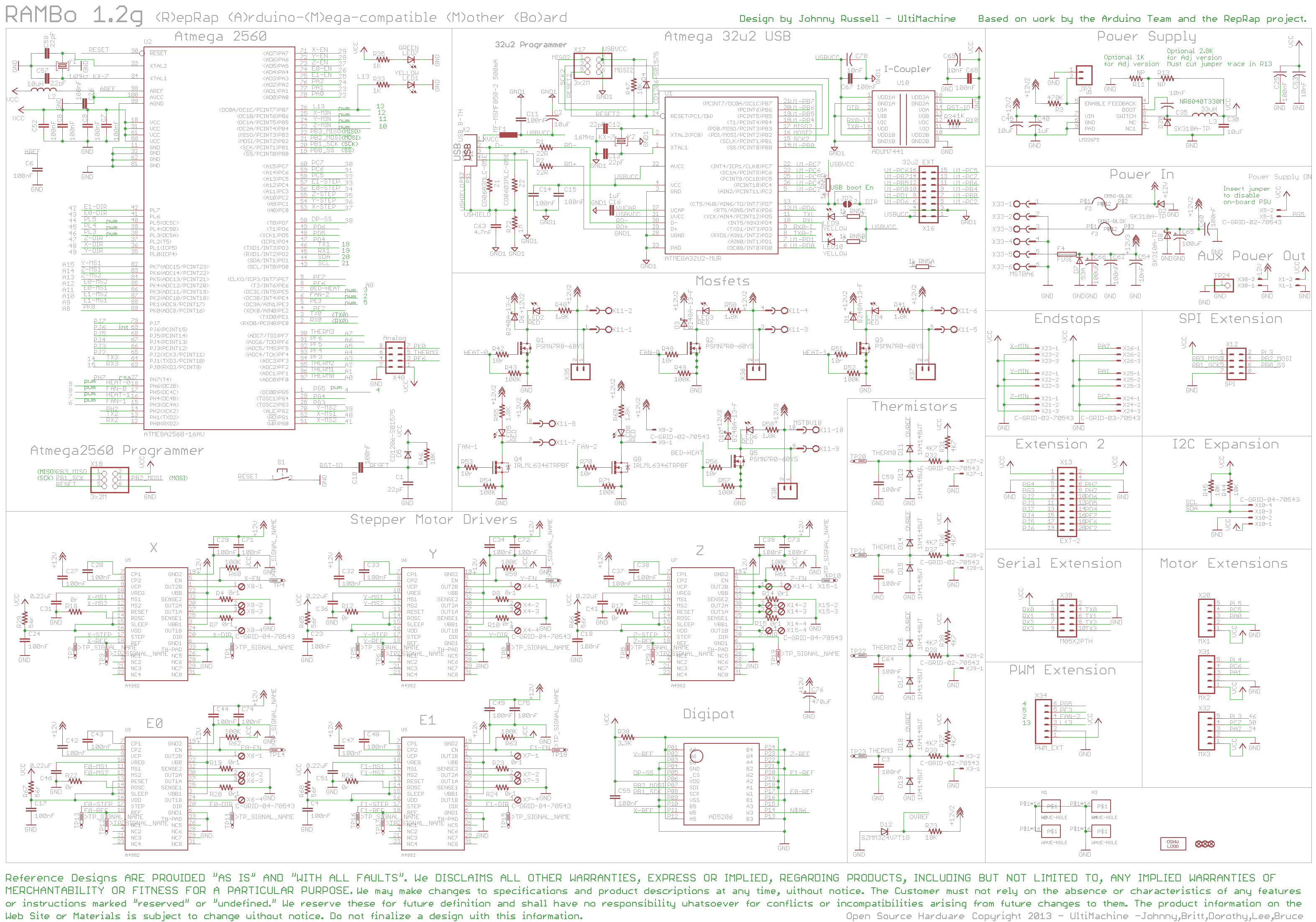
If you'll look at the schematic (http://reprap.org/mediawiki/images/9/91 ... ematic.png is the one I'm looking at. I believe pin assignments are the same on all versions of the board.).
See the upper left corner where the Atmega 2560 is. On the right side of the chip box you'll find:
25 X-MIN pwm 12
24 Y-MIN pwm 11
23 Z-MIN pwm 10
The first number is the physical pin number on the chip.
Then the signal name of that pin for the rambo. If you look on the right side of the schematic, you'll see the endstop section where those signals are used.
pwm, indicating the pin is pwm capable...it is nice to have that in the schematic, it saves you looking it up elsewhere.
The last number is the digital pin number assignment for software purposes. This is the number you'll need to know when making software modifications. Again, nice of them to put it on the schematic for reference.
If that all made sense to you, perhaps the rest of the schematic makes more sense now as well.
Fan0 should be P8, not P6.
There is no conflict between analog pin 2 (physical pin 95 on the schematic) and digital pin 2 (physical pin 6 on the schematic). Like I said before, you just have to "know" that it's an analog number you're defining. I believe the temperature inputs are the only analog inputs you'll find in pins.h
To be clear, PWM usage of a pin is a digital pin function, so it's referred to by the digital pin numbering.
Re: RAMBo Pins
Thanks for the reply.
I use the schematic in http://reprap.org/mediawiki/images/9/91 ... ematic.png" onclick="window.open(this.href);return false;
and the chart in http://reprap.org/wiki/Rambo_development" onclick="window.open(this.href);return false;
Ardunio pin # 8 is fan-0. pin#6 is fan-1. I can use the (M45 P<pin number> S<0-255>) for addressing pin6(which if fan-1) and pin7 (which is heat 1).
However the M45 command does not work for Heat0 or fan0, I assume because that are defined in pins.h (since I only currently have one extruder/hotend).
Now, for fan-2. My RAMBo has a 2 pin fan-2 header just to the left of the extruder1 fan header.
.......Look at your 2560 schematic, lower right corner..........6 PE4 ( OC3B/INT4 ) Digital pin 2 (PWM) Fan 2, PWM-Ext 4
Fan-2 is on Pin2, but in the Pins.h I have the heatbed temperature on Pin 2 #define TEMP_BED_PIN 2
Now, back to the 2560 schematic, that is the 95 PF2 ( ADC2 ) Analog pin 2 Thermistor 2
So, is it possible to even use the Fan-2 header? I just do not see in the the code how it differentiates between an analog input and a digital input....... fan-2 seems to be used by the heatbed thermistor?
Re: RAMBo Pins
This is like red pill/blue pill. They're both pills, but you know they're different because one is red and one is blue.
Yes, they're both #2, but one is a digital #2 and one is an analog #2. They may look the same to you, but they're different because of context.
You're lucky I'm a code jockey, or this would be too much trouble:
pins.h:#define TEMP_BED_PIN 2
Configuration.h:#define HEATED_BED_SENSOR_PIN TEMP_BED_PIN
Repetier.h:#define BED_ANALOG_CHANNEL ACCOMMA5 HEATED_BED_SENSOR_PIN
Repetier.h:#define BED_SENSOR_INDEX HEATED_BED_SENSOR_PIN
Repetier.h:#define ANALOG_INPUT_CHANNELS {EXT0_ANALOG_CHANNEL EXT1_ANALOG_CHANNEL EXT2_ANALOG_CHANNEL EXT3_ANALOG_CHANNEL EXT4_ANALOG_CHANNEL EXT5_ANALOG_CHANNEL BED_ANALOG_CHANNEL}
Extruder.cpp:const uint8 osAnalogInputChannels[] PROGMEM = ANALOG_INPUT_CHANNELS;
Extruder.cpp:TemperatureController heatedBedController = {NUM_EXTRUDER,HEATED_BED_SENSOR_TYPE,BED_SENSOR_INDEX,0,0,0,0,0,HEATED_BED_HEAT_MANAGER
,0,HEATED_BED_PID_INTEGRAL_DRIVE_MAX,HEATED_BED_PID_INTEGRAL_DRIVE_MIN,HEATED_BED_PID_PGAIN,HEATED_BED_PID_IGAIN,HEATED_BED_PID
_DGAIN,HEATED_BED_PID_MAX,0,0,0,{0,0,0,0}
Extruder.cpp: currentTemperature = (1023<<(2-ANALOG_REDUCE_BITS))-(osAnalogInputValues[sensorPin]>>(ANALOG_REDUCE_BITS)); // Convert to 10 bit result
*** note, I'm leaving a lot out...the actual reading of the analog inputs is in an interrupt routine (in HAL.cpp), which is a pretty advanced software/hardware concept if you're new to programming. Plus most of the code ignores the higher level libraries that implement things like analogRead and does i/o at the register level.
Re: RAMBo Pins
I just noticed there is already Servo support built into Repetier. You'll have to enable it in Configuration.h, and maybe redefine the assigned pin(s). After that, you should be able to control servos with Gcode.
Repetier.ino: - M340 P<servoId> S<pulseInUS> : servoID = 0..3, Servos are controlled by a pulse with normally between 500 and 2500 with 1500ms in center position. 0 turns servo off.
I've never tried it, but there you go. What you want to do may turn out to be easy.
Repetier.ino: - M340 P<servoId> S<pulseInUS> : servoID = 0..3, Servos are controlled by a pulse with normally between 500 and 2500 with 1500ms in center position. 0 turns servo off.
I've never tried it, but there you go. What you want to do may turn out to be easy.
Re: RAMBo Pins
I don't see servo support in Configuration.h nor Configuration.h:#define HEATED_BED_SENSOR_PIN TEMP_BED_PIN
It looks to me that the MX extensions are all free, and that is like 9 pins...........
I'd like to know why I cannot switch the Fan-2 header on or off.
You are way ahead of me...........I don't know what you are telling me....I don't have a clue to where the Repiter code is.
It looks to me that the MX extensions are all free, and that is like 9 pins...........
I'd like to know why I cannot switch the Fan-2 header on or off.
You are way ahead of me...........I don't know what you are telling me....I don't have a clue to where the Repiter code is.
Re: RAMBo Pins
Hiram, did you see my post on FAN 2 this week?
Pin 2 for the fan is digital and not the same as the analog pin 2 for hot bed thermistor. It is confusing that Arduino numbers both sets of pins starting from 0 but that's the way it is.
Pin 2 for the fan is digital and not the same as the analog pin 2 for hot bed thermistor. It is confusing that Arduino numbers both sets of pins starting from 0 but that's the way it is.
Sublime Layers - my blog on Musings and Experiments in 3D Printing Technology and Art
Start Here:
A Strategy for Successful (and Great) Prints
Strategies for Resolving Print Artifacts
The Eclectic Angler
Re: RAMBo Pins
What version of Repetier are you using? .91 has this in Configuration.h:
Code: Select all
/* Servos

If you need to control servos, enable this feature. You can control up to 4 servos.
Control the servos with
M340 P<servoId> S<pulseInUS>
servoID = 0..3
Servos are controlled by a pulse width normally between 500 and 2500 with 1500ms in center position. 0 turns servo off.

WARNING: Servos can draw a considerable amount of current. Make sure your system can handle this or you may risk your hardware!
*/

#define FEATURE_SERVO false
// Servo pins on a RAMPS board are 11,6,5,4
#define SERVO0_PIN 11
#define SERVO1_PIN 6
#define SERVO2_PIN 5
#define SERVO3_PIN 4
Sublime Layers - my blog on Musings and Experiments in 3D Printing Technology and Art
Start Here:
A Strategy for Successful (and Great) Prints
Strategies for Resolving Print Artifacts
The Eclectic Angler
Re: RAMBo Pins
I don't know where Repiter Configuration.h is. I can't find it.
* Rambo Pin Assignments
******************************************************************/
#ifndef __AVR_ATmega2560__
#error Oops! Make sure you have 'Arduino Mega 2560' selected from the 'Tools -> Boards' menu.
#endif
#define X_STEP_PIN 37
#define X_DIR_PIN 48
#define X_MIN_PIN 12
#define X_MAX_PIN 24
#define X_ENABLE_PIN 29
#define X_MS1_PIN 40
#define X_MS2_PIN 41
#define Y_STEP_PIN 36
#define Y_DIR_PIN 49
#define Y_MIN_PIN 11
#define Y_MAX_PIN 23
#define Y_ENABLE_PIN 28
#define Y_MS1_PIN 69
#define Y_MS2_PIN 39
#define Z_STEP_PIN 35
#define Z_DIR_PIN 47
#define Z_MIN_PIN 10
#define Z_MAX_PIN 30
#define Z_ENABLE_PIN 27
#define Z_MS1_PIN 68
#define Z_MS2_PIN 67
#define HEATER_BED_PIN 3
#define TEMP_BED_PIN 2
#define HEATER_0_PIN 9
#define TEMP_0_PIN 0
#define HEATER_1_PIN 7
#define TEMP_1_PIN 1
#define HEATER_2_PIN -1
#define TEMP_2_PIN -1
#define E0_STEP_PIN 34
#define E0_DIR_PIN 43
#define E0_ENABLE_PIN 26
#define E0_MS1_PIN 65
#define E0_MS2_PIN 66
#define E1_STEP_PIN 33
#define E1_DIR_PIN 42
#define E1_ENABLE_PIN 25
#define E1_MS1_PIN 63
#define E1_MS2_PIN 64
#define DIGIPOTSS_PIN 38
#define DIGIPOT_CHANNELS {4,5,3,0,1} // X Y Z E0 E1 digipot channels to stepper driver mapping
#define SDPOWER -1
#define SDSS 53
#define LED_PIN 13
#define FAN_PIN 8
#define PS_ON_PIN 4
#define KILL_PIN -1
#define SUICIDE_PIN -1 //PIN that has to be turned on right after start, to keep power flowing.
#endif
#ifndef KNOWN_BOARD
#error Unknown MOTHERBOARD value in configuration.h
#endif
//List of pins which to ignore when asked to change by gcode, 0 and 1 are RX and TX, do not mess with those!
#define _E0_PINS E0_STEP_PIN, E0_DIR_PIN, E0_ENABLE_PIN, HEATER_0_PIN,
#if EXTRUDERS > 1
#define _E1_PINS E1_STEP_PIN, E1_DIR_PIN, E1_ENABLE_PIN, HEATER_1_PIN,
#else
#define _E1_PINS
#endif
#if EXTRUDERS > 2
#define _E2_PINS E2_STEP_PIN, E2_DIR_PIN, E2_ENABLE_PIN, HEATER_2_PIN,
#else
#define _E2_PINS
#endif
#ifdef DISABLE_MAX_ENDSTOPS
#define X_MAX_PIN -1
#define Y_MAX_PIN -1
#define Z_MAX_PIN -1
#endif
#define SENSITIVE_PINS {0, 1, X_STEP_PIN, X_DIR_PIN, X_ENABLE_PIN, X_MIN_PIN, X_MAX_PIN, Y_STEP_PIN, Y_DIR_PIN, Y_ENABLE_PIN, Y_MIN_PIN, Y_MAX_PIN, Z_STEP_PIN, Z_DIR_PIN, Z_ENABLE_PIN, Z_MIN_PIN, Z_MAX_PIN, LED_PIN, PS_ON_PIN, \
HEATER_BED_PIN, FAN_PIN, \
_E0_PINS _E1_PINS _E2_PINS \
TEMP_0_PIN, TEMP_1_PIN, TEMP_2_PIN, TEMP_BED_PIN }
Re: RAMBo Pins
That is Pins.h you posted. In the same directory/folder as Pins.h is Configuration.h. You should see it as one of the tabs in Arduino IDE or just go into the folder to find it.
Sublime Layers - my blog on Musings and Experiments in 3D Printing Technology and Art
Start Here:
A Strategy for Successful (and Great) Prints
Strategies for Resolving Print Artifacts
The Eclectic Angler
Re: RAMBo Pins
Yes.
I don't have a Repetier Configuration.h, it is Marlin Configuration.h
Anyways, let me start over.........because I am so confused that I forgot what it is that I want to do.......
I have an Airwolf 3dxl.
I want to change the single hot end to dual e3d hotends, and add an extruder(bowden set-up) and I think I will need to add a servo to wipe the nozzles. and have independent hot-end fans but also have a PLA fan......
For now, I just want to get the hotends and fans working, and worry about the servo-wiper later.......
Thanks.......
Re: RAMBo Pins
hiram, you should have mentioned that earlier! When you post in the SeeMeCNC forum, we're going to assume a SeeMeCNC printer unless otherwise stated!
You should have no problems configuring Marlin to use the RAMBo to control 2 hot ends and extruders and your fans.
Plug your hot ends into Heat 0 and Heat 1 on RAMBo. Your E3D cooling fan or fans plug into Fan 0 (and Fan 1 if you are using 2 separate fans but why not put both on the same circuit). Your parts cooling fan, which people either mount on the effector/carriage or on the bed blowing in the part can go in the FAN 2 plug. Your PINS.h in Marlin is already set up for this. But, you do have to tell Marlin that you have 2 extruders and hot ends and how they are configured. Best to go to another group for that, not much expertise on Marlin here, we are all pretty much Repetier firmware on our Rostock Maxes and Orion printers.
Sublime Layers - my blog on Musings and Experiments in 3D Printing Technology and Art
Start Here:
A Strategy for Successful (and Great) Prints
Strategies for Resolving Print Artifacts
The Eclectic Angler
Re: RAMBo Pins
ahhhhhhhhh I am so happy now that I know what is going on, I never heard of a SeeMe printer, I found this site by searching for the RAMBo board.............
I think I have a few hairs left in my head that I didn't pull out........
I thought you meant Repiter host, which I do use.....
I think I have a few hairs left in my head that I didn't pull out........
I thought you meant Repiter host, which I do use.....