Couple issues I've run into with assembly of my H1.1
Did anyone else get 6 nuts that are a different thread pitch than the threaded rod with their missing parts delivery? I can't figure out what they are for and they won't thread onto anything. I don't have enough hardware to assemble the Z-axis screws so I'm guessing they may have been meant for that.
Has anyone figure out the mounting for all the gears and idlers yet? I'm cross referencing two different photos of the H1.1 and they don't appear to be the same. At least I don't have enough parts to configure it the way I think it should be setup.
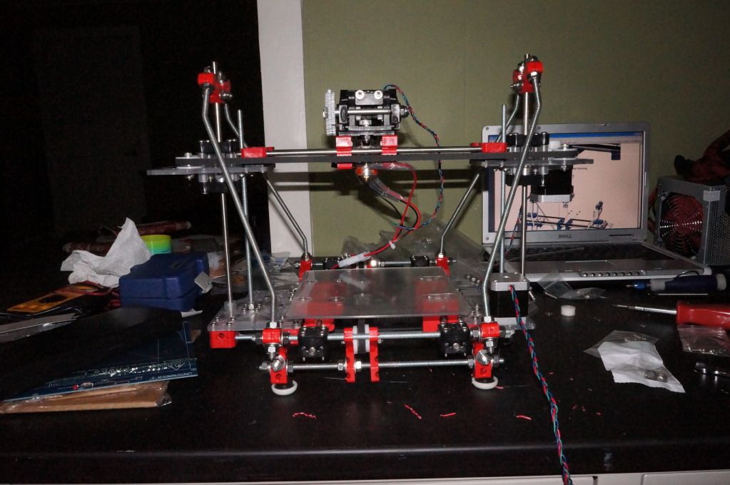
Pretty close to fully assembled just have a few things left to figure out.
Couple Questions
-
Pizzapie500
- Noob
- Posts: 3
- Joined: Mon Aug 06, 2012 7:45 pm
Re: Couple Questions
I bought the H1.1 full kit, but I haven't started to assemble it yet. My missing parts just came today, and I don't think I got six nuts. I got (3) 1/4" lock nuts, but that's about it  I'm still missing (2) 1/4"-20 x 10 1/2" L threaded rods. I looked at the H1 instructions and my H1.1 parts, since there's over 150 less parts, it's hard to tell what to do.
Re: Couple Questions
I's say assembly is about 95% the same. The big parts reduction is mostly due to two things.
The bar clamps use screws instead of bolts which deletes the need for 48 nuts.
Linear bearings replace a lot of the ball bearings that were used before so there is a big reduction in bearings and mounting hardware for them.
The bar clamps use screws instead of bolts which deletes the need for 48 nuts.
Linear bearings replace a lot of the ball bearings that were used before so there is a big reduction in bearings and mounting hardware for them.

Re: Couple Questions
[*]Extruder Drive Unit
The extruder hot end is assembled, but required hi temp copper RTV silicone from autoparts store.
The extruder hot end is assembled, but required hi temp copper RTV silicone from autoparts store.
~PartDaddy
SeeMeCNC Owner & Founder
Blackpoint Engineering is SeeMeCNC
Since 1996
SeeMeCNC Owner & Founder
Blackpoint Engineering is SeeMeCNC
Since 1996
Re: Couple Questions
Machine Assembly:
Starting with the base of the machine. Orient parts as shown. The #6 x 1 sheet metal screws hold together cross bar clamps. All threaded rods are 1/4-20 x 12"L. R4ZZ ball bearing held in by #6 x 1/2" sheet metal screws and will require one drop of super glue from the bottom side to secure them.
Starting with the base of the machine. Orient parts as shown. The #6 x 1 sheet metal screws hold together cross bar clamps. All threaded rods are 1/4-20 x 12"L. R4ZZ ball bearing held in by #6 x 1/2" sheet metal screws and will require one drop of super glue from the bottom side to secure them.
- Attachments
-
~PartDaddy
SeeMeCNC Owner & Founder
Blackpoint Engineering is SeeMeCNC
Since 1996
SeeMeCNC Owner & Founder
Blackpoint Engineering is SeeMeCNC
Since 1996

Re: Couple Questions
I had the same problem jasco. I think they are 24 t/in instead of 20 t/in but i fixed that by taping them with a 1/4-20 tap.
Re: Couple Questions
PartDaddy wrote:Machine Assembly:
Starting with the base of the machine. Orient parts as shown. The #6 x 1 sheet metal screws hold together cross bar clamps. All threaded rods are 1/4-20 x 12"L. R4ZZ ball bearing held in by #6 x 1/2" sheet metal screws and will require one drop of super glue from the bottom side to secure them.
haha i think somebody has the manual
Re: Couple Questions
Hope this means we are going to get flooded with instructions over the next couple days.
So far so good on my assembly.
So far so good on my assembly.
Re: Couple Questions
does anyone know how the belt clamps work?
Re: Couple Questions
They fold in half with two screws through them and belt in between. Toothed side of belt goes against toothed side of clamp
Re: Couple Questions
The idlers for your x-axis. Starting on the z-axis plates do you have them plastic washer-bearing-plastic washer-metal washer? That is where I'm stuck. Seems like they should be elevated above the z-axis plates more.AndGorew wrote:almost done
Matt
Re: Couple Questions
That should be right. They should be that way because the pully on the x axis motor goes on upside down. with the teeth closest to the motor.
Re: Couple Questions
jasco13 wrote:They fold in half with two screws through them and belt in between. Toothed side of belt goes against toothed side of clamp
that works for the y axis belts but not for the x axis belts. There is no holes for the x axis belt clamps to be screwed to. do we have to drill those holes ourselves?
Re: Couple Questions
That is the only way I can see to do it. I looked at that for about 15 minutes last night trying to figure out another way and looking at the pics posted on the SeeMeCNC storefront site it looks like we will have to drill. Just hope I get it right the first time.AndGorew wrote:jasco13 wrote:They fold in half with two screws through them and belt in between. Toothed side of belt goes against toothed side of clamp
that works for the y axis belts but not for the x axis belts. There is no holes for the x axis belt clamps to be screwed to. do we have to drill those holes ourselves?
Re: Couple Questions
jasco13 wrote:That is the only way I can see to do it. I looked at that for about 15 minutes last night trying to figure out another way and looking at the pics posted on the SeeMeCNC storefront site it looks like we will have to drill. Just hope I get it right the first time.
You'll get it right.
If you're like me, tho, you may have to redo it after a bit. Mine worked great till I had a bit of time on the machine, and the belt stretched or the idlers broke in or something, and the belt got a little loose. I just poked another hole in the belt and put the screw back in. Bing, bang, boom, good as new! Eventually I used a small hose clamp, straightened it out, and put it inline on one side. Now it's a simple screw adjustment to adjust the belt, if I ever have too....
Home made Cnc, 2 CarveWright wood carving machines, Laser cutter/engraver, large format vinyl cutter, large format printer, and now a 3D Printer! Oh, and a shop full of equipment to take large expensive pieces of wood and turn them into scrap and sawdust.
Re: Couple Questions
Doug we both mean drill 4 holes for the clamps to screw to instead of just the belts screwed to it. that way you dont have to worry about stretching out a hole in the belt
Re: Couple Questions
Ahhh! I see now!AndGorew wrote:Doug we both mean drill 4 holes for the clamps to screw to instead of just the belts screwed to it. that way you dont have to worry about stretching out a hole in the belt
Home made Cnc, 2 CarveWright wood carving machines, Laser cutter/engraver, large format vinyl cutter, large format printer, and now a 3D Printer! Oh, and a shop full of equipment to take large expensive pieces of wood and turn them into scrap and sawdust.
Re: Couple Questions
All hardware 1/4" size is 1/4-20.
It is possible for the stainless steel to gull. So a small drop of lube is recommended. If you turn the nut or bolt slow, it usually won't gull. (Gull, get a burr, seize, or lock up when threading together).
It is possible for the stainless steel to gull. So a small drop of lube is recommended. If you turn the nut or bolt slow, it usually won't gull. (Gull, get a burr, seize, or lock up when threading together).
~PartDaddy
SeeMeCNC Owner & Founder
Blackpoint Engineering is SeeMeCNC
Since 1996
SeeMeCNC Owner & Founder
Blackpoint Engineering is SeeMeCNC
Since 1996
Re: Couple Questions
H1.1 Step 2
~PartDaddy
SeeMeCNC Owner & Founder
Blackpoint Engineering is SeeMeCNC
Since 1996
SeeMeCNC Owner & Founder
Blackpoint Engineering is SeeMeCNC
Since 1996
Re: Couple Questions
All parts are supposed to be 1/4-20, but I was sent 6 nuts that are a finer thread and not 1/4-20. Spent $6 at lowes today replacing those nuts and some missing lock nuts.PartDaddy wrote:All hardware 1/4" size is 1/4-20.
It is possible for the stainless steel to gull. So a small drop of lube is recommended. If you turn the nut or bolt slow, it usually won't gull. (Gull, get a burr, seize, or lock up when threading together).
Matt
Re: Couple Questions
Here's a picture of the belt clamps of my own invention.
I recommend pre-drilling a 3/32 hole. 1/16 hole will work too.
The #4 x 1/2" sheet metal screws are for belt clamps (the length of screw is measured under the head of the screw, and as a side note, flat-head screw lengths are measured over-all length)
No1 screwdriver
do not over tighten
I recommend pre-drilling a 3/32 hole. 1/16 hole will work too.
The #4 x 1/2" sheet metal screws are for belt clamps (the length of screw is measured under the head of the screw, and as a side note, flat-head screw lengths are measured over-all length)
No1 screwdriver
do not over tighten
~PartDaddy
SeeMeCNC Owner & Founder
Blackpoint Engineering is SeeMeCNC
Since 1996
SeeMeCNC Owner & Founder
Blackpoint Engineering is SeeMeCNC
Since 1996
Re: Couple Questions
~PartDaddy
SeeMeCNC Owner & Founder
Blackpoint Engineering is SeeMeCNC
Since 1996
SeeMeCNC Owner & Founder
Blackpoint Engineering is SeeMeCNC
Since 1996
Re: Couple Questions
The only way a wrong size nut got in the kit is if my vendor has some accidentally mixed in. Sorry about this. I am going to look through inventory to try to fix this. Thanks for pointing it out.
~PartDaddy
SeeMeCNC Owner & Founder
Blackpoint Engineering is SeeMeCNC
Since 1996
SeeMeCNC Owner & Founder
Blackpoint Engineering is SeeMeCNC
Since 1996
Re: Couple Questions
Mechanical Assembly Complete. Going to start on the wiring tomorrow. I've got races this weekend so probably won't have it up and running until next week, but I'm getting closer.
[img]http://i1267.photobucket.com/albums/jj5 ... C03190.jpg[/img]
[img]http://i1267.photobucket.com/albums/jj5 ... C03190.jpg[/img]