My Rostock Max is due to be delivered tomorrow! So, in order to save time, I'm creating my build thread tonight in anticipation.
All of my high resolution photos for the following posts can be found here: Rostock Max photos.
Cheers,
Michael
Mhackney's Rostock Max
Mhackney's Rostock Max
Sublime Layers - my blog on Musings and Experiments in 3D Printing Technology and Art
Start Here:
A Strategy for Successful (and Great) Prints
Strategies for Resolving Print Artifacts
The Eclectic Angler
Re: Mhackney's Rostock Max
It's heeeeerrrrreeee! Arrived right on schedule. To put things in perspective, here is the box with a 6" ruler on top. This is a big box!
[img]http://mhackney.zenfolio.com/img/s2/v71 ... 5004-3.jpg[/img]
[img]http://mhackney.zenfolio.com/img/s2/v71 ... 5004-3.jpg[/img]
Sublime Layers - my blog on Musings and Experiments in 3D Printing Technology and Art
Start Here:
A Strategy for Successful (and Great) Prints
Strategies for Resolving Print Artifacts
The Eclectic Angler
Re: Mhackney's Rostock Max
The important 1st step: unboxing.
I can use these to package my fly reel kits:
[img]http://mhackney.zenfolio.com/img/s8/v85 ... 6936-3.jpg[/img]
First layer of peanuts removed:
[img]http://mhackney.zenfolio.com/img/s8/v77 ... 4580-3.jpg[/img]
The power supply:
[img]http://mhackney.zenfolio.com/img/s2/v71 ... 4466-3.jpg[/img]
RAMBo controller, steppers and electronics stuff. Even the wire is included in this kit:
[img]http://mhackney.zenfolio.com/img/s8/v83 ... 3910-3.jpg[/img]
Couldn't tell you what this is but I'm sure to find out soon:
[img]http://mhackney.zenfolio.com/img/s8/v78 ... 4356-3.jpg[/img]
Even in plastic bag the Onyx hot bed is a thing of beauty! Also the Smart Controller LCD display:
[img]http://mhackney.zenfolio.com/img/s8/v82 ... 4172-3.jpg[/img]
and underneath everything, the laser cut parts and aluminum struts:
[img]http://mhackney.zenfolio.com/img/s8/v80 ... 4028-3.jpg[/img]
Looks like everything survived the trip from SeeMeCNC central to my lair.
The box has that fresh "laser cut wood" fragrance when you open it!
Cheers,
Michael
Sublime Layers - my blog on Musings and Experiments in 3D Printing Technology and Art
Start Here:
A Strategy for Successful (and Great) Prints
Strategies for Resolving Print Artifacts
The Eclectic Angler
Re: Mhackney's Rostock Max
No parts inventory in my box, Steve probably thinks I'm smarter than I am!
It can be found on the RepRap site: http://reprap.org/wiki/Rostock_MAX
It can be found on the RepRap site: http://reprap.org/wiki/Rostock_MAX
Sublime Layers - my blog on Musings and Experiments in 3D Printing Technology and Art
Start Here:
A Strategy for Successful (and Great) Prints
Strategies for Resolving Print Artifacts
The Eclectic Angler
Base Assembly coming along
Firstly, removing all of the tape and protective backing is probably the most time consuming part of the build! I am removing and de-taping parts as I need them rather than all at once. It makes it easier for me to locate the parts.
Here is the base coming along:
[img]http://mhackney.zenfolio.com/img/s8/v81 ... 5602-3.jpg[/img]
one Base Plate #69355
six plastic feet assemblies
three Tri Supports #68352
three TSlot Supports #68377
three Motor Mounts #68364
one Power Supply Retainer #68356
And I now know what that roll of white plastic is for - its a cover for the base unit, it is flexible to wrap around the base.
UPDATE: now that I've completed assembly, I recommend reading through my entire build for retrospective tips! One I will add here though - I recommend assembling the hot end NOW so the silicone has plenty of time to cure. See my post Hot End Setup and Wiring for instructions.
Cheers,
Michael
Sublime Layers - my blog on Musings and Experiments in 3D Printing Technology and Art
Start Here:
A Strategy for Successful (and Great) Prints
Strategies for Resolving Print Artifacts
The Eclectic Angler
Re: Mhackney's Rostock Max
The Cover Brackets #68361 with my kit are different than those shown in the v 1.9 Rostock Max User Guide. They do not have the row of holes down the middle.
[img]http://mhackney.zenfolio.com/img/s8/v84 ... 7370-3.jpg[/img]
Took me a bit of time to find them because I was keying on that feature.
seven Cover Brackets #68361
One other suggestion - it would be helpful to include the # of each part or assembly. I am going to edit my posts above to include that and will do so as I progress.
cheers,
Michael
Sublime Layers - my blog on Musings and Experiments in 3D Printing Technology and Art
Start Here:
A Strategy for Successful (and Great) Prints
Strategies for Resolving Print Artifacts
The Eclectic Angler
Re: Mhackney's Rostock Max
I'm a tap wrench sort of guy. Used a 10-32 tap wrench to cut the threads in the Cover Brackets:
[img]http://mhackney.zenfolio.com/img/s8/v74 ... 7168-3.jpg[/img]
[img]http://mhackney.zenfolio.com/img/s8/v74 ... 7168-3.jpg[/img]
Sublime Layers - my blog on Musings and Experiments in 3D Printing Technology and Art
Start Here:
A Strategy for Successful (and Great) Prints
Strategies for Resolving Print Artifacts
The Eclectic Angler
Cover Brackets and Panels installed
one Electronics Mount #68358 serves double duty as a door. The hinges are on the left as you face it with the laser etched text facing out - you should be able to read it right side up! The hinges are simple - the panel has tabs on its left end that engage large holes in the base 0 creating a hinge.
[img]http://mhackney.zenfolio.com/img/s8/v76 ... 6282-3.jpg[/img]
one Support Panel #68357 also serves double duty as a door. The text also should face out and upright and the hinges are on the left.
[img]http://mhackney.zenfolio.com/img/s1/v56 ... 6514-3.jpg[/img]
Regards,
Michael
[img]http://mhackney.zenfolio.com/img/s8/v76 ... 6282-3.jpg[/img]
one Support Panel #68357 also serves double duty as a door. The text also should face out and upright and the hinges are on the left.
[img]http://mhackney.zenfolio.com/img/s1/v56 ... 6514-3.jpg[/img]
Regards,
Michael
Sublime Layers - my blog on Musings and Experiments in 3D Printing Technology and Art
Start Here:
A Strategy for Successful (and Great) Prints
Strategies for Resolving Print Artifacts
The Eclectic Angler
Note to self...
Note to self...
Anytime you see a notch for a nut to slide into, go ahead and install the nut! That way you do not have to take everything apart to install nuts in difficult to reach places.
Anytime you see a notch for a nut to slide into, go ahead and install the nut! That way you do not have to take everything apart to install nuts in difficult to reach places.
Sublime Layers - my blog on Musings and Experiments in 3D Printing Technology and Art
Start Here:
A Strategy for Successful (and Great) Prints
Strategies for Resolving Print Artifacts
The Eclectic Angler
Lower Idlers
There are nine idler assemblies each made up of a 608 bearing #35065 and two 608 Cheapskate Idler Bearing Spacers #68340. These just snap together. I added a drop of light machine oil to each bearing before assembling.
Six of these idler assemblies are used on the base - the other three are installed on the top when we get there. The assemblies fit between the space in the supports. The back assembly is slightly higher than the front.
[img]http://mhackney.zenfolio.com/img/s8/v80 ... 7344-3.jpg[/img]
My kit had nine 1 3/4" #6 Philips head screws for these. I put a #6 washer on each side and used a nylon lock nut. Leave these loose so you can finiggle the supports around to attach the Base Top in the next step.
Again, this is easiest to do now while you can gain easy access to the screws.
Cheers,
Michael
Sublime Layers - my blog on Musings and Experiments in 3D Printing Technology and Art
Start Here:
A Strategy for Successful (and Great) Prints
Strategies for Resolving Print Artifacts
The Eclectic Angler
Base Top
With the idler assemblies in place one Base Top #68351 can be installed. This is tricky since there are lots of tabs on the supports that must line up in the slots. Gene's suggestion in the Assembly Guide is a good one - once you have a slot/tab lined up in popped in place, screw it loosely together at that point. I started with the seven Cover Bracket locations around the perimeter. Once I had these loosely screwed together, it was straight forward to get the others lined up and held in place with a screw. Then, tighten the screws down to draw the joints together. Place a screw in all of the countersunk holes on the top, tighten them all then flip and do the same for the bottom.
Top:
[img]http://mhackney.zenfolio.com/img/s4/v65 ... 5282-3.jpg[/img]
Bottom:
[img]http://mhackney.zenfolio.com/img/s8/v82 ... 5366-3.jpg[/img]
Top:
[img]http://mhackney.zenfolio.com/img/s4/v65 ... 5282-3.jpg[/img]
Bottom:
[img]http://mhackney.zenfolio.com/img/s8/v82 ... 5366-3.jpg[/img]
Sublime Layers - my blog on Musings and Experiments in 3D Printing Technology and Art
Start Here:
A Strategy for Successful (and Great) Prints
Strategies for Resolving Print Artifacts
The Eclectic Angler
High Res photos
Just wanted to provide a link to the high res version of these photos. There will likely be more photos on my gallery than I'll post too.
Rostock Max photos
Cheers,
Michael
Rostock Max photos
Cheers,
Michael
Sublime Layers - my blog on Musings and Experiments in 3D Printing Technology and Art
Start Here:
A Strategy for Successful (and Great) Prints
Strategies for Resolving Print Artifacts
The Eclectic Angler
Onyx hotbed
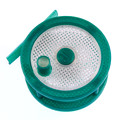
I wanted to dry fit the Onyx hotbed. Looks easy enough to install. It has six special holes that are not marked, so I annotated this photo:
[img]http://mhackney.zenfolio.com/img/s8/v74 ... 0922-3.jpg[/img]
The Onyx kit comes with a snowflake shaped spacer that insulates the bed from the base:
[img]http://mhackney.zenfolio.com/img/s8/v82 ... 2530-3.jpg[/img]
and here it is sitting on the spacer:
[img]http://mhackney.zenfolio.com/img/s2/v73 ... 2734-3.jpg[/img]
Note that the electrical connections are in back by the Z axis marking. That's so the wiring can be routed through this slot:
[img]http://mhackney.zenfolio.com/img/s8/v81 ... 2300-3.jpg[/img]
The hardware kit with the Onyx has T nuts that need to be installed at the six locations and six nylon spacers. I need to go find and read the installation posts/videos. I'll include that info in my thread too. There's also a resister, thermistor and LED to solder in place.
regards,
Michael
Sublime Layers - my blog on Musings and Experiments in 3D Printing Technology and Art
Start Here:
A Strategy for Successful (and Great) Prints
Strategies for Resolving Print Artifacts
The Eclectic Angler
-
Polygonhell
- ULTIMATE 3D JEDI
- Posts: 2430
- Joined: Mon Mar 26, 2012 1:44 pm
- Location: Redmond WA
Re: Mhackney's Rostock Max
There is one gotcha IMO, because the onyx sits over the slot, and the clearance is low, you'll want to strip enough of the outer insulation from the provided wire off so that it's just the inner wires come through the slot to the onyx.
Printer blog http://3dprinterhell.blogspot.com/
Re: Mhackney's Rostock Max
Thanks, and in looking at it, the nylon spacers must go between the base top and the snowflake spacer because the later covers the slot. If that's the case, there should be plenty of room for the hotbed wires since the spacers are about 1/8" thick.
I'll insulate the bottom of my bed also. Forget the name of the stuff, I talked about it in my H-1 thread last year.
cheers,
Michael
I'll insulate the bottom of my bed also. Forget the name of the stuff, I talked about it in my H-1 thread last year.
cheers,
Michael
Sublime Layers - my blog on Musings and Experiments in 3D Printing Technology and Art
Start Here:
A Strategy for Successful (and Great) Prints
Strategies for Resolving Print Artifacts
The Eclectic Angler
Re: Mhackney's Rostock Max
This is how I seated the T-nuts for the hotbed - I used two of the nylon spacers and a screw to draw the nut into the melamine.
[img]http://mhackney.zenfolio.com/img/s4/v62 ... 8318-3.jpg[/img]
[img]http://mhackney.zenfolio.com/img/s4/v62 ... 8318-3.jpg[/img]
Sublime Layers - my blog on Musings and Experiments in 3D Printing Technology and Art
Start Here:
A Strategy for Successful (and Great) Prints
Strategies for Resolving Print Artifacts
The Eclectic Angler
Onyx electronics
<><><><><><><><><><><><><><><><><><><><><><><><><><><><><><><><><><><><><><><><><><>
UPDATE 3/1/2014:
When I assembled my Onyx, it made sense to put the resistor and led on top where the silkscreen indicates. That was before borosilicate glass was available. Now that we have glass print surfaces, the glass covers this pad so it makes sense to mount everything on the back side as per Gene's manual. I cheated when I fabricated my aluminum heat dissipator and cut out clearance on it. You need to provide clearance anyway to minimize the chance of shorting (I prefer not to rely solely on Kapton tape for this.
<><><><><><><><><><><><><><><><><><><><><><><><><><><><><><><><><><><><><><><><><><>
There are 3 components to install on the Onyx table. The thermistor goes into the center hole from underneath - not at the location on the connection pad at the perimeter of the table - that's for the connection to your controller. Make sure the leads of the thermistor do not touch the metal plated center hole. Leaving the leads their full length makes it easier to position the thermistor. I will fill this area with some RTV silicone once I'm done with the wiring to keep the thermistor in position.
[img]http://mhackney.zenfolio.com/img/s8/v81 ... 5242-3.jpg[/img]
Then clip the leads:
[img]http://mhackney.zenfolio.com/img/s8/v75 ... 5120-3.jpg[/img]
The resistor and LED are soldered to the top of the board on the marked pads. A couple of notes:
[img]http://www.pmptech.ca/wp-content/upload ... 8/LED.jpeg[/img]
After soldering, clip the leads.
[img]http://mhackney.zenfolio.com/img/s8/v85 ... 5174-3.jpg[/img]
cheers,
Michael
UPDATE 3/1/2014:
When I assembled my Onyx, it made sense to put the resistor and led on top where the silkscreen indicates. That was before borosilicate glass was available. Now that we have glass print surfaces, the glass covers this pad so it makes sense to mount everything on the back side as per Gene's manual. I cheated when I fabricated my aluminum heat dissipator and cut out clearance on it. You need to provide clearance anyway to minimize the chance of shorting (I prefer not to rely solely on Kapton tape for this.
<><><><><><><><><><><><><><><><><><><><><><><><><><><><><><><><><><><><><><><><><><>
There are 3 components to install on the Onyx table. The thermistor goes into the center hole from underneath - not at the location on the connection pad at the perimeter of the table - that's for the connection to your controller. Make sure the leads of the thermistor do not touch the metal plated center hole. Leaving the leads their full length makes it easier to position the thermistor. I will fill this area with some RTV silicone once I'm done with the wiring to keep the thermistor in position.
[img]http://mhackney.zenfolio.com/img/s8/v81 ... 5242-3.jpg[/img]
Then clip the leads:
[img]http://mhackney.zenfolio.com/img/s8/v75 ... 5120-3.jpg[/img]
The resistor and LED are soldered to the top of the board on the marked pads. A couple of notes:
- Some folks solder these underneath so they can put a full round glass build surface on the hot bed. I plan to cut the glass with a flat at the back to match the Onyx so I can put the components on top.
- You want the LED to be visible so you can see when the bed is in a heating cycle. On top like I've done it is easy. If you mount below, leave the leads longer so you can bend the LED up to position it.
- If you solder the components on the back side, don't let the leads protrude through the top surface.
[img]http://www.pmptech.ca/wp-content/upload ... 8/LED.jpeg[/img]
After soldering, clip the leads.
[img]http://mhackney.zenfolio.com/img/s8/v85 ... 5174-3.jpg[/img]
cheers,
Michael
Sublime Layers - my blog on Musings and Experiments in 3D Printing Technology and Art
Start Here:
A Strategy for Successful (and Great) Prints
Strategies for Resolving Print Artifacts
The Eclectic Angler
Stepper Motor connections
The RAMBo board I got with my Rostock came with connectors and wiring. The connectors have a positive latch, a really nice feature. The connectors on the RAMPS boards are simple friction fit, a potential point of failure. The RAMBo designer did good on this! The connectors are also polarized. Terminal 1 is marked by a little triangle on the side opposite the latch as you can see here:
[img]http://mhackney.zenfolio.com/img/s8/v79 ... 7308-3.jpg[/img]
Wire the leads from the motor like:
1 - red
2 - blue
3 - green
4 - black
If you are using your own motors the colors may vary. You may also have 6 or 8 wires on your motors. If so, here is a good overview on how to wire these: Stepper Motors Wiring Connections. You do want to wire your steppers Bipolar. I typically wire Bipolar Half Coil on my 6 lead steppers on other machines.
[img]http://mhackney.zenfolio.com/img/s8/v81 ... 6262-3.jpg[/img]
I twisted the leads together before crimping on the connections. Here is a nice tutorial on How to Crimp Connectors.
NOTE: I am going to replace those "set screws" with real set screws!
Cheers,
Michael
Sublime Layers - my blog on Musings and Experiments in 3D Printing Technology and Art
Start Here:
A Strategy for Successful (and Great) Prints
Strategies for Resolving Print Artifacts
The Eclectic Angler
Stepper Motor install
I'm picky about my wiring so I have not extended the Z stepper wiring yet. I'll dry fit the stepper and RAMBo and then determine how much extra wire needs to be added and report the total length here.
The upright next to the stepper mounts has an oval slot. This is for the wiring to pass through, so position the wires coming out of the motor towards the middle of the base:
[img]http://mhackney.zenfolio.com/img/s11/v3 ... 9360-3.jpg[/img]
Here is the X stepper installed with the wiring passing through the slot:
[img]http://mhackney.zenfolio.com/img/s3/v43 ... 9246-3.jpg[/img]
Sublime Layers - my blog on Musings and Experiments in 3D Printing Technology and Art
Start Here:
A Strategy for Successful (and Great) Prints
Strategies for Resolving Print Artifacts
The Eclectic Angler
-
Polygonhell
- ULTIMATE 3D JEDI
- Posts: 2430
- Joined: Mon Mar 26, 2012 1:44 pm
- Location: Redmond WA
Re: Mhackney's Rostock Max
I'd strongly recommend using some Kapton tape or other insulation under the leads of the bed thermistor where it enters the hole, the center hole for whatever reason I'd through plated, and it's very easy to short one or both of the thermistor wires.
I had to remove my bed after installation to fix this, I had only one wire shorted to the hole and it resulted in what appeared to be a ballpark fine resistance reading on my meter, but a 250c reading at room temperature in the firmware.
I had to remove my bed after installation to fix this, I had only one wire shorted to the hole and it resulted in what appeared to be a ballpark fine resistance reading on my meter, but a 250c reading at room temperature in the firmware.
Printer blog http://3dprinterhell.blogspot.com/
Re: Mhackney's Rostock Max
I've had good experience with the copper RTV silicone to insulate the thermistor leads on hot ends - as long as you let it cure unperturbed! I might scrape the plating off with an Xacto knife too.
Cheers,
Michael
Cheers,
Michael
Sublime Layers - my blog on Musings and Experiments in 3D Printing Technology and Art
Start Here:
A Strategy for Successful (and Great) Prints
Strategies for Resolving Print Artifacts
The Eclectic Angler
Onyx install quick update
Here's a photo of the thermistor with the Permatex Ultra Copper silicone on it to insulate and hold it in place:
[img]http://mhackney.zenfolio.com/img/s8/v82 ... 7922-3.jpg[/img]
I did remove the metal plating around the rim and inside the hole with an Xacto knife before adding the silicone. That should prevent shorts.
Cheers,
Michael
[img]http://mhackney.zenfolio.com/img/s8/v82 ... 7922-3.jpg[/img]
I did remove the metal plating around the rim and inside the hole with an Xacto knife before adding the silicone. That should prevent shorts.
Cheers,
Michael
Sublime Layers - my blog on Musings and Experiments in 3D Printing Technology and Art
Start Here:
A Strategy for Successful (and Great) Prints
Strategies for Resolving Print Artifacts
The Eclectic Angler
Stepper Motor install tips
Here are a couple of tips to make it easier to install the stepper motors.
Use a long Philips screwdriver, a 4" blade length will work great.
Use a pair of needle nose pliers to hold the screw. You can hold it between the uprights as shown in the photo. Then, line up the screwdriver head with the screw head by looking through the access hole on the right side upright.
Install the screw at the bottom front first. it's the easiest one to access and once in place it will hold the motor in place.
[img]http://mhackney.zenfolio.com/img/s8/v74 ... 6354-3.jpg[/img]
I use a little Loctite on my stepper screws, you could also use a lockwasher as Gene describes in the manual.
cheers,
Michael
Sublime Layers - my blog on Musings and Experiments in 3D Printing Technology and Art
Start Here:
A Strategy for Successful (and Great) Prints
Strategies for Resolving Print Artifacts
The Eclectic Angler
Upgraded Power Supply
I've been using these power supplies I get off eBay for a number my other printers and projects. 12 volts at 30Amps. They have the umph for driving hot ends and heated beds as well as the steppers.
[img]http://mhackney.zenfolio.com/img/s2/v70 ... 9182-3.jpg[/img]
[img]http://mhackney.zenfolio.com/img/s1/v54 ... 8982-3.jpg[/img]
Make sure to check the input AC voltage switch, this one was set to 220V, all of the others I've purchased were 120 by default. It pays to check on ANY power supply you use.
The supply will require a little pedestal mount but there is plenty of room for it. I will also have to add an on/off switch.
[img]http://mhackney.zenfolio.com/img/s8/v83 ... 6048-3.jpg[/img]
(and don't forget, high res versions of all photos are on my photo site.)
Sublime Layers - my blog on Musings and Experiments in 3D Printing Technology and Art
Start Here:
A Strategy for Successful (and Great) Prints
Strategies for Resolving Print Artifacts
The Eclectic Angler
RAMBo installation and a tip!
The RAMBo installed easily on the inside of the door, stepper motor connectors down. I placed both of the plastic spacers between the door and board like Gene described in the manual. Now I can add the extension to the Z motor cable and report back the total length.
[img]http://mhackney.zenfolio.com/img/s8/v78 ... 4084-3.jpg[/img]
ANd now for the tip! I picked up a few of these serving trays at the Dollar Store for, well, a $1 each. They are a great way to organize small parts and tools for a project. I think the dark colors are better since you can see steel and aluminum parts easier in them.
[img]http://mhackney.zenfolio.com/img/s8/v83 ... 4192-3.jpg[/img]
Sublime Layers - my blog on Musings and Experiments in 3D Printing Technology and Art
Start Here:
A Strategy for Successful (and Great) Prints
Strategies for Resolving Print Artifacts
The Eclectic Angler