4 years ago I built an H1.1.
Now I am working on an Rostock Max V3. I am currently about 14.5 hours in and have mounted the top motors. This is probably a reasonable rate to shoot for by people with limited mechanical skills. If you're mhackney you are probably asking why I needed to build 3 of them. (For comparison, the H1.1 took me 50 hours.)
Comments so far:
Hot end (took me 5 hours; took mhackney 1.5 hours).
Tools:
If you don't have a good #1 philips screwdriver, with a hardened tip and a reasonably large diameter handle, then you won't be able to screw it together with poor keyboard-damaged wrists like mine. $5 at a hardware store. Don't take a random phillips driver from your 30-tools-for-$10 chinese harbor freight tool kit and expect it to work.
While you're at the hardware store, pick up some blue loctite, vice-grip pliers that can gape at least 1.5 inches, a 2" c clamp, lineman's crimpers.
Step 9: The metal parts on my hot end kit came all lightly screwed together as a dry fit (or maybe to ensure that all components were packed properly). Take them all apart befor proceeding to assembly.
Step 28: Before installing the hotend PCB, it would probably be best to bend the thermal fuse and heater wires so they go through the appropriate holes (seen in steps 30,31). Easier than taking wires sticking straight out and trying to bend them through the holes withotu stressing the other connections and components.
step 33: Trim all 4 wires. You don't have to flush cut them, so you can leave a small amount extra in case you have to rework later.
Step 38: This is where you use the good #1.
Base assembly (6 hours for me.)
Bearing bushing assembly
I have found the technique to get the bearings into the bushings. There are 9 of these in the top and bottom assembly (and additional ones in the cheapskates: but I don't know how hard those will be.) You can't just press them in with your bare hands; you have to be a tool-using animal.
Vice-grips are the pliers-like tool that have the fancy linkage so that when you close them they snap into position and hold a fixed, adjustable, distance apart. Another advantage of vice grips is that the jaws tend to move along a straight line of closure, instead of having a swinging scissoring motion like ordinary pliers. This lets you apply force more evenly. If you have a bench vice you may find that easier than vice-grips and/or c-clamp.
Get some large coins (quarters work, but Nixon's face is on some 2016 $1 coins, and the tool use is likely to mar the coins).
Adjust the vice-grips so that when they snap closed the jaws loosely hold a coin-bushing-coin stack. Now you don't have to worry about the tool crushing the plastic bushing.
Stack: coin, bushing, bearing, coin. Note that the bushing has a large diameter opening on one side and a smaller diameter on the other. The bearing goes on the large side. (You may think this is obvious, but I am writing these notes for someone like me.)
Squeeze the stack with the vice grips so the bearing is driven evenly into the bushing. It is OK to do cycles of squeeze-release-adjust to prevent it from cocking. There is a loud satisfying click from the vice-grips when you are done with that step.
Take an 11 mm socket and put it on the bearing rim, positioning it so it doesn't hit the bushing hole. Make a coin, bushing+bearing, socket, coin stack and put it in the jaws of the c-clamp. Turn the C-clamp to push the bearing all the way into the bushing. You should feel increased resistance when it seats.
Take the bushing+bearing assembly out fo the clamp and inspect. There is likely to be a thin sliver of plastic visible, which you should remove.
Repeat as necessary.
Nylocks
Vice grips are good for squeezing the nylock nuts into the various plastic pieces. They should end up with the flats of the hex along the cavity walls and the edges pointing up. (Orientation matters: the screw enters from the flat side and protrudes through the domed side).
Hot plate
Use the long (2.2 meter) black wire and the shorter (700 mm) red wire for this. You will need the 2.2 meter red wire later.
Top assembly (3.5 hours so far).
There is an allen key along with the pulleys and grub screws you attach to the motor. On mine, it was the wrong size. There is another allen key in the extruder parts bag. I haven't yet checked whether it is the right size. (This is where the blue loctite is used. I think that Blue means that you can take it apart later if you need to.)
Check that you are bending the switch terminals in the correct direction, pay close attention to where the switch button is on the picture. (And remove the levers.)
When you mount the switches, the screws (which are the fine-thread machine screws and not the coarse-thread sheet metal screws) poke through the motor mounts by quite a bit.
And that's where I am at 14.5 hours. Next: mounting the RAMBO.
dmpalmer's Rostock Max V3 build
Re: dmpalmer's Rostock Max V3 build
Rambo and wires (2 hours)
Endstop switches: Connect to the two prongs that you bent outward earlier. The video says to use the 'outer terminals of the switch', so I connected to the terminals that were closest to the outside of the Rostock. Instead you want the two terminals that are closest to the outside of the switch.
Step 15: You stick a piece of filament into the extruder to align the hobbed wheel before tightening the grub screw. However, you have to shift it a bit out of alignment to fit the allen key in past the red push button arms. It should settle back to alignment eventually though.
The clear plastic of the extruder is showing stress whitening wher the roller hits it. Fortunately that shouldn't be a long term problem because after assembly the force that was stressing it is taken by the hobbed wheel (directly or though the filament depending on whether it is loaded.
Step 16: The USB bulkhead connector is not included? In a $1k kit? Seems a strange thing to leave out even if it is not required when using a Raspberry.
-
Eaglezsoar

- ULTIMATE 3D JEDI
- Posts: 7185
- Joined: Sun Apr 01, 2012 5:26 pm
Re: dmpalmer's Rostock Max V3 build
Thanks for all the neat tips!
“ Do Not Regret Growing Older. It is a Privilege Denied to Many. ”
Re: dmpalmer's Rostock Max V3 build
Seven bucks on Amazon.
Re: dmpalmer's Rostock Max V3 build
Good tools make all the difference! Good quality screwdrivers are essential. I also have a pair of "alligator" vice grips. These were great for gripping the locknuts and pushing them into slots.
I used a bench vice to press the bearings in the shells. They made a loud "POP" when they seated in.
I agree with Eagle, some good tips. Especially the hotend step 28. It would be much easier to place the PCB over the various wires than try to force them in place.
I agree on the USB port. I suspect it was a supply issue. They aren't even offered as an option on their website but the hole was cut for the part. The part # is listed and I found them on Amazon: Tripp-Lite-Hi-Speed-Extension-U025-001-PM I have one on order.
Sublime Layers - my blog on Musings and Experiments in 3D Printing Technology and Art
Start Here:
A Strategy for Successful (and Great) Prints
Strategies for Resolving Print Artifacts
The Eclectic Angler
Re: dmpalmer's Rostock Max V3 build
"outer terminals" means the terminal at either end of the switch body.dmpalmer wrote:Rambo and wires (2 hours)
Endstop switches: Connect to the two prongs that you bent outward earlier. The video says to use the 'outer terminals of the switch', so I connected to the terminals that were closest to the outside of the Rostock. Instead you want the two terminals that are closest to the outside of the switch.
g.
Delta Power!
Defeat the Cartesian Agenda!
http://www.f15sim.com - 80-0007, The only one of its kind.
http://geneb.simpits.org - Technical and Simulator Projects
Defeat the Cartesian Agenda!
http://www.f15sim.com - 80-0007, The only one of its kind.
http://geneb.simpits.org - Technical and Simulator Projects
Re: dmpalmer's Rostock Max V3 build
Final assembly(5 hours so far)
Cheapskate carriages
Vice grips (or bench vice) and coins to squeeze the two sides of the bushings to each bearing.
I'm going to call the armature that holds two bearings and allows them to pivot a 'dihedral' to emphasize the angle it has. Always be aware of its angle. Study the images and animations to see which way the angle goes. When you put the two armpieces of each dihedral together, make sure the angle is in the same direction. I was very careful about this and almost always got it right.
To put the two armpieces together, lightly sand the circular edge at the tip of each pin to give it a bit of a taper. Otherwise the pin is likely to mushroom and prevent the pin from going into the hole. Vice-grips again (gently, g a little way on one side, then a little way on the other) to squeeze the pieces together.
The flat-head screws that hit the endstops are longer than the 1/2" called out in the parts list. That just stole 8 mm of height from the build volume.
Step 2: DO NOT apply two crimp terminals to the ends of the red and two crimps to the end of the black. I waited to apply any crimps until the tower was assembled and I was ready to connect. Sometimes (this time) I can avoid mistakes in advance.
Step 3. After putting the white wires in the X tower, I couldn't get the black wire all the way down the beam hole no matter how hard I pushed, and the wire ended up helical. I eventually ran the red wire through that tower instead. (The red wire was a replacement I bought at the hardware store which (although still 12 gauge) was thinner than the supplied red wire.) My Rostock Max will have non-standard wiring, but I will survive. (I did carefully label the black heatbed wire and the black power-ground wire. Probably a good idea anyway.)
Steps 5-10: I slacked a lot of screws and nuts to get things loose enough to get it together, then tightened them back up. Probably a good idea anyway to release residual stresses. I will do a final ritual tightening of everything once it is all assembled.
Make sure that each carriage slides smoothly up and down the tower and that the flathead screw has a good contact with the endstop switches. Feel/hear the switches click.
Step 8. You would have to be very careless to put one of the carriages with the white dumbell on the outside of the tower. You would have to be more careless than I was to install a carriage upside down.
More to do tomorrow.
Re: dmpalmer's Rostock Max V3 build
I basically followed the build as-is and added some edits and comments as I saw things that needed clarification.
On Step 2, I put the crimps on first. Once I had the wires routed through the towers and the towers installed, I pulled the slack up to the top - leaving enough in the base so as not to strain the wires. This worked fine.
I ran all 3 wires (2 small white and 1 large black) together and they pushed through fine. I did smooth the wires as I pushed to minimize friction and reduce twisting.
Installing the towers requires a little finesse with the t-slot nuts. The photo in step 5 is perfect. That is exactly the gap you need and note that the top of the nut leans in a little. If you make the gap too large or small, it makes it more difficult to start the tower. Line the bottom ones up at the same time. On 2 of my 3 the tower slid right in on the top and lower t-slot nuts in one smooth motion. Once I had all towers installed and loosely fixed, I used several machinists squares to make sure everything was plumb as I tightened them.
On Step 8, you do not put the dumbbells on until after the carriages are installed so an inexperienced person may not know which way they go. I had to look at them with due consideration before installing. That's why I added the bullet!
Sublime Layers - my blog on Musings and Experiments in 3D Printing Technology and Art
Start Here:
A Strategy for Successful (and Great) Prints
Strategies for Resolving Print Artifacts
The Eclectic Angler
Re: dmpalmer's Rostock Max V3 build
The instructions don't include hooking up the hot bed. (Thermister to Thermister1 on RAMBO, black wire to Heat2Bed on RAMBO via screw terminal block.)
Is that correct?
I have added that step to the dozuki.
Is that correct?
I have added that step to the dozuki.
Re: dmpalmer's Rostock Max V3 build
I recall that it is in the video on wiring the RAMBo maybe?
Sublime Layers - my blog on Musings and Experiments in 3D Printing Technology and Art
Start Here:
A Strategy for Successful (and Great) Prints
Strategies for Resolving Print Artifacts
The Eclectic Angler
Re: dmpalmer's Rostock Max V3 build
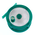
What is this piece? It is in the bag with the belt clamps.
Re: dmpalmer's Rostock Max V3 build
No idea! Didn't use them. Might be a V2 holdover.
Please go to my build thread and check my posts on the HE280 fan connectors and make sure yours are good. The factory installed the fan connectors backwards on my PCB.
Please go to my build thread and check my posts on the HE280 fan connectors and make sure yours are good. The factory installed the fan connectors backwards on my PCB.
Sublime Layers - my blog on Musings and Experiments in 3D Printing Technology and Art
Start Here:
A Strategy for Successful (and Great) Prints
Strategies for Resolving Print Artifacts
The Eclectic Angler
Re: dmpalmer's Rostock Max V3 build
Hotbed wiring is not in the "Wiring the RAMBo" video for part 3 step 10. (And it couldn't be there because the top assembly isn't installed yet.)
It is in the hotend whip video. The answer is that the hot bed thermister goes to Thermistor2 (not 1)
It is in the hotend whip video. The answer is that the hot bed thermister goes to Thermistor2 (not 1)
-
Mac The Knife
- ULTIMATE 3D JEDI
- Posts: 1409
- Joined: Sun May 11, 2014 6:18 pm
Re: dmpalmer's Rostock Max V3 build
I believe it was said that the spare parts are for installing the new carriages to the old arms that uses the steel axles and universal joints. They have to get rid of them some how. 
R-Max V2
Eris
Folger Tech FT-5 R2
Eris
Folger Tech FT-5 R2
Re: dmpalmer's Rostock Max V3 build
More final assembly (2 more hours, plus time to ask questions and update the Dozuki and build log a bit)
Wiring installed and ready. Belts threaded, clamped and tensioned. (I am impressed by the belt mechanism and the ease of control over tension.)
In Part 1 step 34, it says to install the 2-pin headers with the flat face toward the hot end. (It is impossible to tell which way the connectors are mounted in the picture due to contrast issues.) That is what I did and the red wires are where the silk screen says +.
Re: dmpalmer's Rostock Max V3 build
Then it sounds like you got it right. Mine were reversed. The flat face was facing out.
Sublime Layers - my blog on Musings and Experiments in 3D Printing Technology and Art
Start Here:
A Strategy for Successful (and Great) Prints
Strategies for Resolving Print Artifacts
The Eclectic Angler
Re: dmpalmer's Rostock Max V3 build
Completed assembly(1 hour)
I couldn't get the spool holder fully installed into the slots on top on one side..
When I move the carriages, lights turn on, indicating that the stepper motors are connected and generating power.
I am now ready to flash the processor.
I couldn't get the spool holder fully installed into the slots on top on one side..
When I move the carriages, lights turn on, indicating that the stepper motors are connected and generating power.
I am now ready to flash the processor.
Re: dmpalmer's Rostock Max V3 build
I tapped the spool holder with a mallet to seat them. Good luck commissioning.
Sublime Layers - my blog on Musings and Experiments in 3D Printing Technology and Art
Start Here:
A Strategy for Successful (and Great) Prints
Strategies for Resolving Print Artifacts
The Eclectic Angler
Re: dmpalmer's Rostock Max V3 build
Calibrated (30 minutes)
I have MacOS Sierra and I had to update to the latest Arduino software. No problems.
Video of calibration recorded, but it looks just like mhackney's.
I have MacOS Sierra and I had to update to the latest Arduino software. No problems.
Video of calibration recorded, but it looks just like mhackney's.
Re: dmpalmer's Rostock Max V3 build
Printing the calibration brick that comes with matterControl, on unadorned glass, standard settings on the standard slicer. SImulating the the stock experience for a first time printer.
Build time to first print: 25 hours[\b].
I like.
Build time to first print: 25 hours[\b].
I like.
Re: dmpalmer's Rostock Max V3 build
What! that's insanely long for that cube. Did you use the MatterSlicer? In looking at the defaults for the 3 slicers MatterControl supports for the Rostock, they all have extremely long retracts at high speed. Use those and you will get a jam. PLA will be worse but even ABS will jam with those defaults.
Sublime Layers - my blog on Musings and Experiments in 3D Printing Technology and Art
Start Here:
A Strategy for Successful (and Great) Prints
Strategies for Resolving Print Artifacts
The Eclectic Angler
Re: dmpalmer's Rostock Max V3 build
Calibration brick: 20.10 x 20.07 x 9.90.
The power supply fan is LOUD. Much louder than it should be.
One other tool I forgot to mention: a spudger is a plastic (or wood) stick. Makes it a lot easier to peel backing paper off the plastic parts. You don't have to worry about getting your fingernail under the paper, just push onto the surface and slide. Since it is not metal you don't have to worry about scratching the surface.
I did break one of the plastic springs on the arms. There's a spare. there are other spares in the kit (screws, nuts, cheapskate bearing and bushings, bowden clips, etc.)
Print a benchy boat now.
Re: dmpalmer's Rostock Max V3 build
It didn't take 25 hours to print the cube. It took 25 hours of assembly etc. time to build the printer. Printing the cube took 30 minutes or so.
I am using the slicer that Mattercontrol bundles, which I guess is matterslicer.
I haven't looked at all of the parameters yet. I haven't found the retraction distance.
I am using the slicer that Mattercontrol bundles, which I guess is matterslicer.
I haven't looked at all of the parameters yet. I haven't found the retraction distance.
Re: dmpalmer's Rostock Max V3 build
Ah! That makes more sense.
You need to look at the advanced slicer settings. MatterControl makes it very difficult to find this stuff.
Settings->Advanced drop down.
You need to look at the advanced slicer settings. MatterControl makes it very difficult to find this stuff.
Settings->Advanced drop down.
Sublime Layers - my blog on Musings and Experiments in 3D Printing Technology and Art
Start Here:
A Strategy for Successful (and Great) Prints
Strategies for Resolving Print Artifacts
The Eclectic Angler
Re: dmpalmer's Rostock Max V3 build
Here is my 3DBenchy. MatterControl/MatterSlicer in PLA with all stock parameters.
And here is my third print, part of a CowTech 3D scanner. My H1.1 was never this good, reliable, or easy to use.