mhackney's Real V3 Build Thread
All Done
I estimate about 16 hrs including photos to complete. Now I get to relearn Repetier.
Sublime Layers - my blog on Musings and Experiments in 3D Printing Technology and Art
Start Here:
A Strategy for Successful (and Great) Prints
Strategies for Resolving Print Artifacts
The Eclectic Angler
-
Eaglezsoar

- ULTIMATE 3D JEDI
- Posts: 7185
- Joined: Sun Apr 01, 2012 5:26 pm
Re: mhackney's Real V3 Build Thread
Good job, as usual. 
“ Do Not Regret Growing Older. It is a Privilege Denied to Many. ”
Re: mhackney's Real V3 Build Thread
This one is 100% stock right now. I did clip all the wires up top and install the proper connectors. I don't like wads of wire.
Sublime Layers - my blog on Musings and Experiments in 3D Printing Technology and Art
Start Here:
A Strategy for Successful (and Great) Prints
Strategies for Resolving Print Artifacts
The Eclectic Angler
Re: mhackney's Real V3 Build Thread
Let me know how you find the accelerometer probe. I have misgivings about running I2C over such a long distance and in close proximity to heater and possibly extruder stepper wires, but if you find it works reliably and you like it, then we can look at adding support for it in RepRapFirmware.

Re: mhackney's Real V3 Build Thread
The lcd "box" certainly looks like an add on. Like they forgot one needed to be added and just made a box for it and slapped it on. Not a polished look. Does it look OK in person?
Re: mhackney's Real V3 Build Thread
@joe, yes it actually looks great in person and it "matches" the carriage covers in design and material. The reset button is nicely designed and integrated too.
@dc42, SeeMeCNC instruct to probe "cold" so there should be no current in the heater or fan wires to the effector. The controller board is on top of the machine (as are the steppers) but the hot end wiring all comes up through a hole away from any stepper wiring. Th run should be around 700 mm or so. Since the stock configuration is identical to what I just described, I'll see how reliably the probe performs.
@dc42, SeeMeCNC instruct to probe "cold" so there should be no current in the heater or fan wires to the effector. The controller board is on top of the machine (as are the steppers) but the hot end wiring all comes up through a hole away from any stepper wiring. Th run should be around 700 mm or so. Since the stock configuration is identical to what I just described, I'll see how reliably the probe performs.
Sublime Layers - my blog on Musings and Experiments in 3D Printing Technology and Art
Start Here:
A Strategy for Successful (and Great) Prints
Strategies for Resolving Print Artifacts
The Eclectic Angler
Some Build Observations and Notes
Firstly, I was very impressed with the overall design, materials and quality of the V3 kit. My first Rostock was an early V1 that I then highly modified so I missed all the advancements through the V2 series. It was great to experience everything first hand in this new kit plus it's new features/design.
A much lower part count was great - especially those melamine parts. Most of them are large and not small ones (tedious to peal the paper protection off). Nuts are easier to insert in the injection molded parts than they were in the melamine parts in the old days too.
Step 1: The HE280 is a nicely integrated system. I look forward to putting it through its paces. I am not a big fan of lots of fans as you can learn by reading my sticky post on fans and my signature links.
Step 2: On the base assembly, installing the bearing covers might be challenging. A bench vise or small arbor press makes it a snap. dmpalmer's technique using a C clamp would be effective and probably the most accessible option. It's only negative is it takes a little longer to do. With a vise it took seconds each.
One of my tower support parts #84408 was over molded and thicker than all the others and the slots were completely filled. I had to thin the tabs on top and bottom so they'd fit the base plate slots. Check yours and get a replacement if you find any like this.
Everything else about the base and power supply wiring went smoothly.
Step 3: more bearings and covers to install!
Installing the endstop switches can be a chore. I recommend pre-tapping the holes with a 2-56 tap if you can. Overdriving the holes is risky if you go too big. Otherwise a high quality screwdriver will get the job done, lubricate with a little vaseline or paraffin will help considerably. The screws can get very hot! and they will protrude out the back about 2mm or so.
I don't like coils of excess wiring. The RAMBo box contains crimp pins and connector housings so if you have a crimp tool, you can easily shorten the endstop and stepper cables and put the correct connectors on them. The stepper connectors are not the correct locking type, they will work but are not keyed and not locked. The connectors provided with the RAMBo are much better and worth the few minutes to install (plus you remove a lot of unneeded wire).
I have a RPi to install but it was not the SeeMeCNC kit (they were out of stock). The mounting hardware for the Pi comes with their kit so you'll need to rig up your own install if you already have a Pi to use. I just have my tacked in with double sided tape for now. I might print some of the pillars SeeMeCNC provides with their kit. The holes in the base plate are offset for these and do not align with the holes in the Pi.
The EZR Struder was a snap to assemble, much much easier than its predecessor. I like the new design a lot too. It's not a Bondtech but I suspect it will perform very well.
As mentioned in dmpalmer's thread, the kit does not come with the USB extension. I suspect there might have been a supply issue. You can get one on Amazon for $6.99 - the Tripp Lite U025-001-PM is the exact part SeeMeCNC specifies.
The LCD case looks fine to my eyes, it does not look like an afterthought. I was rather impressed with how it assembled and fit and I like the transparent case to see the electronics behind. It will "show well" at my 3D printing presentations and demos!
The last step 20 in this section is the most important, always listen to GeneB.
Step 4: The carriage bearing covers are easy to install by hand. Good thing since there are a lot of them!
Installing the towers requires some wiggling and giggling and patience. Nothing new here, this is how the V1s assembled too.
Installing the top also required a bit of giggling and wiggling bit went pretty smoothly.
The new belt tensioning mechanism using the stepper mounts much like my CNC machines is very nice. Routing the belts was a lot easier than I recall with the V1. And the new belt retainer clips are the bee's knees, very nicely designed and convenient.
The top plate install was probably the single most difficult step for me. Getting all the tabs lined up with the slots took some patience and persistence (and yes, wiggling and giggling too).
I really like the new locking clips for the Bowden tubes. I'm glad they sent a lot extra in my kit! I'll use them on my other machines.
Overall Impressions
This looks to be a very capable printer with a much refined design and parts list. Assembly was straightforward - especially considering how the overall complexity of a 3D printer can be daunting for folks. I really like the new bed mounting and recessed bed. I am not a fan of over constrained bed attachment - the V3 maintains its 6 point attachment - but I'll try it as-is and form an opinion later. It's easy enough remove 3 and get an ideal 3 point attachment, so that's a plus!
I'm looking forward to seeing what the new stock hotend is capable of, the EZR Extruder, and the new accelerometer probe. I'll suffer with RAMBo and Repetier for now and as long as I can! Once you've experienced Duet and dc42 firmware, it's REALLY difficult to go back.
But the build is complete and it's on to commissioning and printing...
A much lower part count was great - especially those melamine parts. Most of them are large and not small ones (tedious to peal the paper protection off). Nuts are easier to insert in the injection molded parts than they were in the melamine parts in the old days too.
Step 1: The HE280 is a nicely integrated system. I look forward to putting it through its paces. I am not a big fan of lots of fans as you can learn by reading my sticky post on fans and my signature links.
Step 2: On the base assembly, installing the bearing covers might be challenging. A bench vise or small arbor press makes it a snap. dmpalmer's technique using a C clamp would be effective and probably the most accessible option. It's only negative is it takes a little longer to do. With a vise it took seconds each.
One of my tower support parts #84408 was over molded and thicker than all the others and the slots were completely filled. I had to thin the tabs on top and bottom so they'd fit the base plate slots. Check yours and get a replacement if you find any like this.
Step 3: more bearings and covers to install!
Installing the endstop switches can be a chore. I recommend pre-tapping the holes with a 2-56 tap if you can. Overdriving the holes is risky if you go too big. Otherwise a high quality screwdriver will get the job done, lubricate with a little vaseline or paraffin will help considerably. The screws can get very hot! and they will protrude out the back about 2mm or so.
I don't like coils of excess wiring. The RAMBo box contains crimp pins and connector housings so if you have a crimp tool, you can easily shorten the endstop and stepper cables and put the correct connectors on them. The stepper connectors are not the correct locking type, they will work but are not keyed and not locked. The connectors provided with the RAMBo are much better and worth the few minutes to install (plus you remove a lot of unneeded wire).
I have a RPi to install but it was not the SeeMeCNC kit (they were out of stock). The mounting hardware for the Pi comes with their kit so you'll need to rig up your own install if you already have a Pi to use. I just have my tacked in with double sided tape for now. I might print some of the pillars SeeMeCNC provides with their kit. The holes in the base plate are offset for these and do not align with the holes in the Pi.
The EZR Struder was a snap to assemble, much much easier than its predecessor. I like the new design a lot too. It's not a Bondtech but I suspect it will perform very well.
As mentioned in dmpalmer's thread, the kit does not come with the USB extension. I suspect there might have been a supply issue. You can get one on Amazon for $6.99 - the Tripp Lite U025-001-PM is the exact part SeeMeCNC specifies.
The LCD case looks fine to my eyes, it does not look like an afterthought. I was rather impressed with how it assembled and fit and I like the transparent case to see the electronics behind. It will "show well" at my 3D printing presentations and demos!
The last step 20 in this section is the most important, always listen to GeneB.
Step 4: The carriage bearing covers are easy to install by hand. Good thing since there are a lot of them!
Installing the towers requires some wiggling and giggling and patience. Nothing new here, this is how the V1s assembled too.
Installing the top also required a bit of giggling and wiggling bit went pretty smoothly.
The new belt tensioning mechanism using the stepper mounts much like my CNC machines is very nice. Routing the belts was a lot easier than I recall with the V1. And the new belt retainer clips are the bee's knees, very nicely designed and convenient.
The top plate install was probably the single most difficult step for me. Getting all the tabs lined up with the slots took some patience and persistence (and yes, wiggling and giggling too).
I really like the new locking clips for the Bowden tubes. I'm glad they sent a lot extra in my kit! I'll use them on my other machines.
Overall Impressions
This looks to be a very capable printer with a much refined design and parts list. Assembly was straightforward - especially considering how the overall complexity of a 3D printer can be daunting for folks. I really like the new bed mounting and recessed bed. I am not a fan of over constrained bed attachment - the V3 maintains its 6 point attachment - but I'll try it as-is and form an opinion later. It's easy enough remove 3 and get an ideal 3 point attachment, so that's a plus!
I'm looking forward to seeing what the new stock hotend is capable of, the EZR Extruder, and the new accelerometer probe. I'll suffer with RAMBo and Repetier for now and as long as I can! Once you've experienced Duet and dc42 firmware, it's REALLY difficult to go back.
But the build is complete and it's on to commissioning and printing...
Sublime Layers - my blog on Musings and Experiments in 3D Printing Technology and Art
Start Here:
A Strategy for Successful (and Great) Prints
Strategies for Resolving Print Artifacts
The Eclectic Angler
Re: mhackney's Real V3 Build Thread
The supports for the Pi grab the sides of the PCB, kind of how they grab the corners of the RAMBo board.
g.
g.
Delta Power!
Defeat the Cartesian Agenda!
http://www.f15sim.com - 80-0007, The only one of its kind.
http://geneb.simpits.org - Technical and Simulator Projects
Defeat the Cartesian Agenda!
http://www.f15sim.com - 80-0007, The only one of its kind.
http://geneb.simpits.org - Technical and Simulator Projects
Re: mhackney's Real V3 Build Thread
Yes, should be easy to print some up. I like that design.
Sublime Layers - my blog on Musings and Experiments in 3D Printing Technology and Art
Start Here:
A Strategy for Successful (and Great) Prints
Strategies for Resolving Print Artifacts
The Eclectic Angler
Commissioning
I'm following the Installing the Firmware Guide on a MacBook running OSX. I'm making small edits to the Guide to support OS X as I go. For instance, there is no driver to install on Linux or OS X!
I dowloaded the linked copy of Arduino IDE and the Repeater firmware zip. Make sure to UNZIP it if you haven't. We recently helped a member who had not unzipped the file and was attempting to install. Took a while to figure out!
Powered on the V3 and she started right up. Then I ran the eeprom_clear sketch.
Next up, configure the firmware. The image I downloaded from the link in the docs had the correct MOTHERBOARD type (301) set but the incorrect PRINTER, so I set that to "5" for V3. Saved the changes then compile and uploaded. I did get a low memory warning when it compiled:
Sketch uses 131,174 bytes (51%) of program storage space. Maximum is 253,952 bytes.
Global variables use 7,295 bytes (89%) of dynamic memory, leaving 897 bytes for local variables. Maximum is 8,192 bytes.
Low memory available, stability problems may occur.
But it completed the upload and as the RAMBo rebooted I saw this:
Followed by:
The temps seem to be right on for my room temperature right now. Next up, testing and calibrating.
I dowloaded the linked copy of Arduino IDE and the Repeater firmware zip. Make sure to UNZIP it if you haven't. We recently helped a member who had not unzipped the file and was attempting to install. Took a while to figure out!
Powered on the V3 and she started right up. Then I ran the eeprom_clear sketch.
Next up, configure the firmware. The image I downloaded from the link in the docs had the correct MOTHERBOARD type (301) set but the incorrect PRINTER, so I set that to "5" for V3. Saved the changes then compile and uploaded. I did get a low memory warning when it compiled:
Sketch uses 131,174 bytes (51%) of program storage space. Maximum is 253,952 bytes.
Global variables use 7,295 bytes (89%) of dynamic memory, leaving 897 bytes for local variables. Maximum is 8,192 bytes.
Low memory available, stability problems may occur.
But it completed the upload and as the RAMBo rebooted I saw this:
Sublime Layers - my blog on Musings and Experiments in 3D Printing Technology and Art
Start Here:
A Strategy for Successful (and Great) Prints
Strategies for Resolving Print Artifacts
The Eclectic Angler
Commissioning Part Deux
I installed MatterControl on OSX - yes, I'm going full-Monty stock setup for now.
Note that I found several versions of the v3Probing.gcode floating around. JJ said this one is correct in a recent post:
I crossed my fingers and hit PRINT. This is the first time anything has run on this machine. I did not test steppers/motion or home switches or anything else. I wanted to see what would happen! I did have my finger on the power switch "just in case". I did take a video to capture whatever happened. And here's the video:
https://youtu.be/REGUXOCi82o
So everything worked first time! Now I need to see how it prints.
Note that I found several versions of the v3Probing.gcode floating around. JJ said this one is correct in a recent post:
Code: Select all
G69 S2 ;Endstop Calibration
M117 ENDSTOPS CALIBRATED
G68 ;Horizontal Radius Calibration
M117 HORIZONTAL RADIUS CALIBRATED
G30 S2 ;Z height calibration
M117 Z Height Calibrated
M500 ;Save values to EEPROM
G4 S2
M117 SAVING CALIBRATIONhttps://youtu.be/REGUXOCi82o
So everything worked first time! Now I need to see how it prints.
Sublime Layers - my blog on Musings and Experiments in 3D Printing Technology and Art
Start Here:
A Strategy for Successful (and Great) Prints
Strategies for Resolving Print Artifacts
The Eclectic Angler
Re: mhackney's Real V3 Build Thread
Now I'm heating things up. The bed came up to 55°C pretty quickly. Hot end also but none of the fans are working. The hot end cooling fan is not coming on nor can I turn on the part cooling fan. The RAMBo cooling fan is running. Time for a little debugging.
Sublime Layers - my blog on Musings and Experiments in 3D Printing Technology and Art
Start Here:
A Strategy for Successful (and Great) Prints
Strategies for Resolving Print Artifacts
The Eclectic Angler
Re: mhackney's Real V3 Build Thread
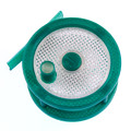
I noticed that when I turn the parts cooling fans on 100% in MC, the red LED in the HE280 shell *next to the blue one) lights. So the signal is getting to the hot end.
Sublime Layers - my blog on Musings and Experiments in 3D Printing Technology and Art
Start Here:
A Strategy for Successful (and Great) Prints
Strategies for Resolving Print Artifacts
The Eclectic Angler
Re: mhackney's Real V3 Build Thread
Well, the fans are wired backwards. Here's what the doc shows:
[img]https://d17kynu4zpq5hy.cloudfront.net/i ... ANI.medium[/img]
Both of the white connector shells on my HE280 PCB are installed 180° from this photo. I got a spare accelerometer PCB to play with but it does not have the connectors installed. But, that allows me to read the silk screen and the terminal + is opposite how mine are installed!
Sublime Layers - my blog on Musings and Experiments in 3D Printing Technology and Art
Start Here:
A Strategy for Successful (and Great) Prints
Strategies for Resolving Print Artifacts
The Eclectic Angler
Re: mhackney's Real V3 Build Thread
The shell does not come off the pins on the PCB so I can't relocate them. But, I can remove the pins and swap them in the connector. There is a little tab that you can pry up with a TINY screwdriver.
One more to swap and I should printing.
Sublime Layers - my blog on Musings and Experiments in 3D Printing Technology and Art
Start Here:
A Strategy for Successful (and Great) Prints
Strategies for Resolving Print Artifacts
The Eclectic Angler
Re: mhackney's Real V3 Build Thread
Ok, completed and tested. Check your HE280 fan connectors!
I calibrated again and now it is heating up for my first print attempt.
I calibrated again and now it is heating up for my first print attempt.
Sublime Layers - my blog on Musings and Experiments in 3D Printing Technology and Art
Start Here:
A Strategy for Successful (and Great) Prints
Strategies for Resolving Print Artifacts
The Eclectic Angler
First Print
Ok, this is impressive. I am forcing myself to use MatterControl and Cura (I won't use MatterSlicer as it is just not up to my work). I tweaked my slicing parameters a bit, the default retract settings are a recipe for disaster. After a few tweaks, I sliced and printed. I am printing on FabLam that I got when I ordered my printer. I used the glass bed to cut the Fablam in a circle and then adhered it with windex and squeegeed out the excess. I conditioned it on the printer at 55°C for 30 minutes. With everything cold, I calibrated using the script, preheated to 55°C (bed) and 190°C (hot end), loaded filament, and hit PRINT. Here's the first layer going down:
https://youtu.be/Z3m8yJR17xs
Mind you this is the first attempt and up until now, the extruder had not even been tested. The first layer looks very good. Excellent adhesion, .2mm consistent thickness (guesstimate based on experience and calibrated eyeballs), and nice smooth tracks. I worked really hard to get my V1 to print this well!
Sublime Layers - my blog on Musings and Experiments in 3D Printing Technology and Art
Start Here:
A Strategy for Successful (and Great) Prints
Strategies for Resolving Print Artifacts
The Eclectic Angler
Re: mhackney's Real V3 Build Thread
Looking good!
I didn't order any Fablam. Should I try just printing directly to the glass (with PLA or ABS+, at what recommended settings?), or should I lay down some 3M blue printer's tape first?
I didn't order any Fablam. Should I try just printing directly to the glass (with PLA or ABS+, at what recommended settings?), or should I lay down some 3M blue printer's tape first?
Re: mhackney's Real V3 Build Thread
Print PLA first on blue painter tape. It's easy and good to practice on.
Use Cura in matter slicer. Then change retract to 1 mm at 35 mm/s. Use 2 perimeters and 30% infill. .2 mm layers for both the first and all layers. That should get you in the ballpark
Use Cura in matter slicer. Then change retract to 1 mm at 35 mm/s. Use 2 perimeters and 30% infill. .2 mm layers for both the first and all layers. That should get you in the ballpark
Sublime Layers - my blog on Musings and Experiments in 3D Printing Technology and Art
Start Here:
A Strategy for Successful (and Great) Prints
Strategies for Resolving Print Artifacts
The Eclectic Angler
Re: mhackney's Real V3 Build Thread
fyi, with the fablam, you print PLA cold and ABS @ 60C. If you try to print "typical" bed temps for ABS, you'll ruin the fablam - no hotter than 60C.
g.
g.
Delta Power!
Defeat the Cartesian Agenda!
http://www.f15sim.com - 80-0007, The only one of its kind.
http://geneb.simpits.org - Technical and Simulator Projects
Defeat the Cartesian Agenda!
http://www.f15sim.com - 80-0007, The only one of its kind.
http://geneb.simpits.org - Technical and Simulator Projects
Re: mhackney's Real V3 Build Thread
Good to know, thanks. I'll try the next one at RT - IF I can get this part off!
Sublime Layers - my blog on Musings and Experiments in 3D Printing Technology and Art
Start Here:
A Strategy for Successful (and Great) Prints
Strategies for Resolving Print Artifacts
The Eclectic Angler
Re: mhackney's Real V3 Build Thread
Here's the finished first print. Not bad at all. No stringing. Those thin pillars are tricky to print and they came out looking pretty good. The issues I see are slicing related and Cura related.
Sublime Layers - my blog on Musings and Experiments in 3D Printing Technology and Art
Start Here:
A Strategy for Successful (and Great) Prints
Strategies for Resolving Print Artifacts
The Eclectic Angler
Re: mhackney's Real V3 Build Thread
I've attached my MatterControl profile for Cura for the part I printed above. Change the extension from .txt to .slice
- Attachments
-
 RostockV3Default.txt
- (4.35 KiB) Downloaded 237 times
Sublime Layers - my blog on Musings and Experiments in 3D Printing Technology and Art
Start Here:
A Strategy for Successful (and Great) Prints
Strategies for Resolving Print Artifacts
The Eclectic Angler
-
DeltaCon
- Printmaster!
- Posts: 616
- Joined: Sat Nov 14, 2015 5:01 am
- Location: Wessem, The Netherlands
- Contact:
Re: mhackney's Real V3 Build Thread
I see that the glass bed is fitted into the top baseplate now. May I ask what is the design decision for that? Why is that better? I think I remember some post about a cold spot in the onyx, which in the end was lead back to a whole in the top base plate, where the onyx got caught by the airstream in the base. In this design the whole onyx is exposed to the fans of the PSU and probably other fans that might get installed later. I can imagine that it leads to uneven temperatures.
I am DeltaCon, I have a delta, my name is Con, I am definitely PRO delta! 
Rostock V2 / E3D Volcano / FSR kit / Duet 0.6
PS.: Sorry for the avatar, that's my other hobby!
Rostock V2 / E3D Volcano / FSR kit / Duet 0.6
PS.: Sorry for the avatar, that's my other hobby!
Re: mhackney's Real V3 Build Thread
Not sure why you would be asking me about SeeMeCNC's design? You could shoot them an email.
Personally, I like it. It keeps the glass from moving laterally when I use my spatula to remove parts. There is a thick injection molded base under the Onyx on the V3 so I can't imagine how a power supply fan could affect the hot bed. The bed heats up pretty fast and stabilizes quickly. I haven't measured but I don't foresee any reason why it wouldn't be consistent across the plate.
Personally, I like it. It keeps the glass from moving laterally when I use my spatula to remove parts. There is a thick injection molded base under the Onyx on the V3 so I can't imagine how a power supply fan could affect the hot bed. The bed heats up pretty fast and stabilizes quickly. I haven't measured but I don't foresee any reason why it wouldn't be consistent across the plate.
Sublime Layers - my blog on Musings and Experiments in 3D Printing Technology and Art
Start Here:
A Strategy for Successful (and Great) Prints
Strategies for Resolving Print Artifacts
The Eclectic Angler