Highcooley's Rostock Max

Start your own build thread so others can see how it's going, and even help out!
Highcooley
Printmaster!
Posts: 121
Joined: Sun Nov 18, 2012 10:23 am

Highcooley's Rostock Max

Post by Highcooley »

Hey everyone

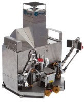
Since my Rostock was finished back last year!!!, in good old 2012, I think it's time to post a couple of images and comment on some details, findings and unsolved problems. Please, pardon the murky and sometimes blurred pictures...my camera has come to age (it's not me, shaking) :D

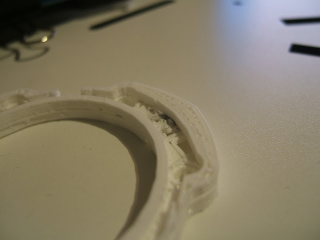
[img]https://lh4.googleusercontent.com/-Ttfq ... CF0479.JPG[/img]

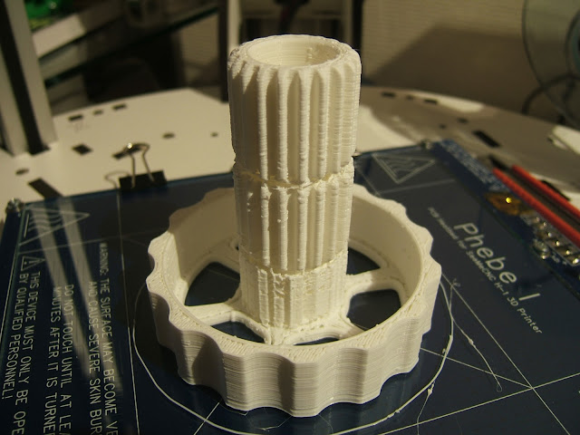
[img]https://lh6.googleusercontent.com/-lULp ... CF0482.JPG[/img] [img]https://lh5.googleusercontent.com/-RFE9 ... CF0493.JPG[/img]
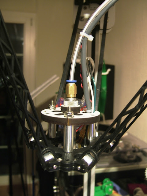
The build
...progress was flawless and fast. Thanks to geneB's manual as well as all the drafts, pictures and findings in the forum, everything worked smoothly. The only little struggle was to get used to the imperial standard screw table, as well as the English names of parts. It took us a while to figure out, that the #4-40 part of a #4-40 3/4" screw has no direct correlation to either diameter or length in inches. A typer in the manual, and the missing of the proper screws to attach the heated bed (we got another set of the screws needed to attach the idlers instead of the smaller ones for the heated bed), caused the confusion.

One finding (not a complaint at all) is, that the build was never possible to be accomplished in 8h as stated. We where four guys building, whereof three are skilled engineers. It took us 9h to get the structure done, install all the actors and sensors, and do the cabling. I built and installed the hot end the next morning, which took me another 4h. However, compared to my last 3D printer build, it was a very fast and more importantly straight forward build. Except for the missing screws, which we had to substitute with metric ones and normal nuts instead of t-nuts, we had nothing to alter or to dig up additional parts. The kit is well manufactured and it is distinguishable, that skilled people with a lot of experience designed it. I was deeply impressed by all the neat construction details, which made life a lot easier.

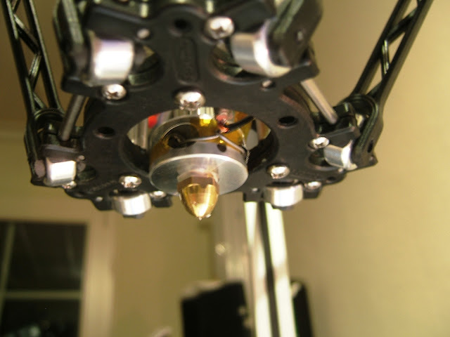
As you can see on the picture of the hot end, we weren't able to get hold of some RTV silicone so far. Capton tape does the job for the moment, and I gently ask you seemecnc guys to consider taking some Permatex RTV silicone on stock for us non US customers. So far, I wasn't able to find a proper substitute, and the local car mechanic never heard about this kind of stuff. Amazon vendors don't really want to ship stuff outside the US or if, then only for immense shipping cost. The only RTV silicone I found, is used as a resin for mold making and is only offered in bulk.
However, this a) causes the hot bed to heat a bit too much, as even five layers of capton don't properly insulate the thermistor and let it cool down too quickly, compared to the PC sheet and b) already blew the fuse once, when the wires scratched through the tape, and accidentally shorted over the heating block. The capton insulation was reinforced and is working, now. On the picture, it looks like the wires would be touching the heating block...that's not the case. They are safely lying on the capton tape with enough safety distance to the aluminium. I hope, I ordered the right mounting form of the FL 5A fuse, as Ultimachine don't say a word about spare parts for the Rambo. However, I went for ESKA SMD-Fuse 2410 220039 -F- 5 A (http://www.conrad.ch/ce/de/product/5298 ... Detail=005), as the measurements seem to fit.

The calibration
...went smoothly, and again, very fast thanks to an almost 100% pre-configured, functional firmware. However, I don't know why we had to invert all three axes after cabling the steppers like mentioned in the manual. May it be, that either the manual or the firmware was written after attaching the timing belt to the outside of the cheapskate carriages, like some builders did? Or was it me, cabling completely wrong anyhow? Fine tuning the E0 steps resulted in quite a different range, which was a bit baffling. I would have to check the exact number later, as I'm currently not in my workshop. But the result turned out to be in the correct range when extruding.

The printing
Now to the hard and unsolved part: We seem to have fit the ball joints a bit too tight, or that's at least, what I think causes the problem. This results in the print head stuttering just a little bit when moving in X direction. The reason why I haven't solved this yet is, that I don't want to damage or slacken any joint connection by unnecessarily dismounting the wrong joints. Any clue, which joints to check first, based on this information?

The other issues are caused by the material and hot end construction. Environmentally and sanitary concerned, I chose to print with PLA instead of ABS, back when I built my first printer. Hence, I only got PLA on stock. Now, different people prefer different materials, and also have different views on which material is easier to print with or causes more problems. As I never tried ABS, I cannot comment on this, but it seems, that there are about the same amount of arguments pro and contra both materials. PLA being the swelling and jamming, and ABS more the warping stuff.
The first finding was: If you want to print PLA, don't use the PS sheet as your bed surface. It sticks like hell and does not pop off during cooling of the print bed, due to similar temperature characteristics of both materials. However, it does not connect to PLA and still can be separated, not resulting in any damage of the PS sheet. This learnt, I went back to the proven to work glass surface. It has to be pretty clean (no greasy finger prints) and is temperature critical in terms of temperature difference between bed and extrusion temperature, resulting in the PLA sticking properly or not.

Next thing is the hot-end. First test prints lead to print properly for about two layers. Afterwards, the filament jammed and refused to extrude at all. If you watch closely, you can see the result in the picture of the hot end: The filament got squeezed up the hot-end outside the PTFE tube and oozed out between the heater block and the nozzle. It's about the worst that can happen to your hot-end, as you have to disassemble and partly clean it, while it is still heated. Otherwise, the thread of the nozzle will simply clog.
After soaking the nozzle in acetone for hours and scratching the PLA out (gently, not to scratch the nozzle), there was still a nasty last bit left:
[img]https://lh3.googleusercontent.com/-dD_c ... CF0502.JPG[/img]

I had to heat the nozzle several times, to pick this last bit out. Cotton buds helped to grab the plastic and finally pull it out.

Cotton buds also proved to be a helpful tool to clean the inner part of the heating block as well as the threads:
[img]https://lh6.googleusercontent.com/-PvrP ... CF0510.JPG[/img]

I heated the block and used a dry cotton bud as well as soaking the cotton bud in acetone but only using it on the cold heating block, to prevent unwanted fire accidents.

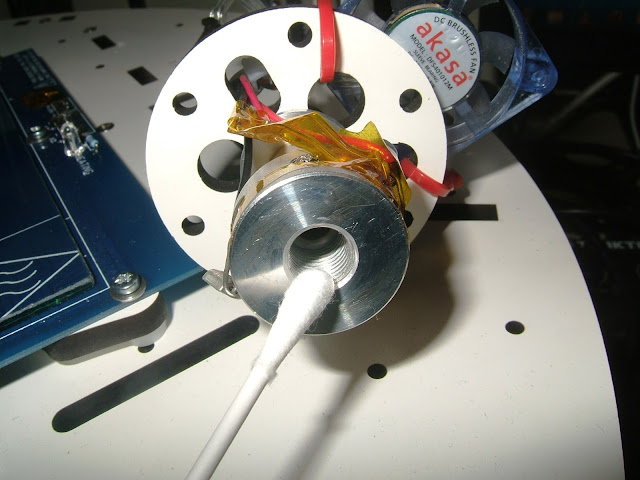
After disassembling and cleaning, it became clear, why the material was able to squeeze out of the tubes:
[img]https://lh4.googleusercontent.com/-BfNE ... CF0512.JPG[/img]

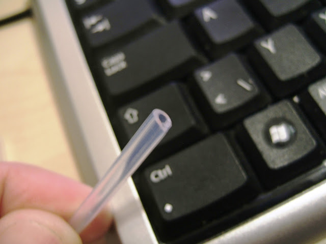
The inner tube was slightly dent at the tip. If this was caused by me, screwing the nozzle in a little bit too much, or if it was the sheer force of the filament, pressing against the nozzle, I don't know. I also noticed, that both, the inner and outer PTFE tubes are at the same length, where as the bottom of the nozzle is slightly gradient due to the drilling.
To solve this and to prevent the inner tube from being squeezed again, I took the following precautions: First, I pushed both tubes down into the nozzle, leading the inner tube to stick out of the outer tube for about 1/2 mm. Then, I cut off the part of the outer tube overlapping the inner tube at the other end of the assembly:
[img]https://lh4.googleusercontent.com/-YHiC ... CF0521.JPG[/img]

This should help to a) equally distribute the force of the nozzle against the tubes to both tubes, and b) prevent the melt being able to push the inner tube back.

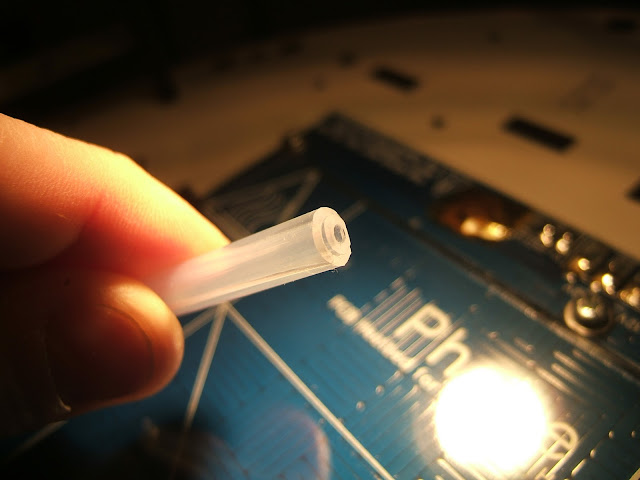
Then, I slightly beveled both tubes, hoping that more surface of the tubes ends will touch the bottom of the nozzle and the inner rim of the inner tube will seal the tube and the nozzle:
[img]https://lh6.googleusercontent.com/-uvfx ... CF0519.JPG[/img]

When assembling the hot-end back together, I had to find out, that there is still a bit of PLA stuck in the thread of the heating block, not willing to be cleaned out. So, I was forced to assemble as the hot-end was heated again. To get a better feeling for the torque applied to the nozzle, I used tweezers, turning them with my wrist, preventing to cause a leverage effect.

The first try ended with the filament stopping to extrude after the first two layers again. That's when I decided to stop experimenting for yesterday. Before shutting down the system, I recognised that I configured a drop in temperature of 10°C between the first and the following layers from 200°C to 190°C. I made this change right before trying out the reassembled hot-end. Therefore, this has nothing to do with prior jamming but could have caused the filament to interrupt extruding due to temperature related shrinkage. We will see tonight. I'll keep you posted.

Thanks for any kind of reply, feedback, tips and tricks. And also congratulations to you seemecnc guys for this awesome kit. Several people advised me not to burn my fingers with a delta printer, as there are still a lot of teething problems with the stiffness of the construction. You proved, that it is possible to build a rigid printer.

Happy printing
Andy

PS@seemecnc: ...your customer service, community activity and will to improve the already good, is exemplary too!
Highcooley
Printmaster!
Posts: 121
Joined: Sun Nov 18, 2012 10:23 am

Re: Highcooley's Rostock Max

Post by Highcooley »

Nope, no luck...same thing happened again with the hot-end. Any input on what to try next? I cannot cut off more PTFE tube, as it would be too short soon.
Polygonhell
ULTIMATE 3D JEDI
Posts: 2430
Joined: Mon Mar 26, 2012 1:44 pm
Location: Redmond WA

Re: Highcooley's Rostock Max

Post by Polygonhell »

Highcooley wrote:Nope, no luck...same thing happened again with the hot-end. Any input on what to try next? I cannot cut off more PTFE tube, as it would be too short soon.
Do you have a fan blowing across the thermal break on the hotend, if you don't PLA will almost certainly jam?
Having sid that the Jams you're showing are in the brass piece usually those will clear if you bump the temperature slightly, it's the ones inside the PTFE tubing that are hard to clear.
The easy way to clear PLA out of the brass is to use a blowtorch or gas burner, acetone doesn't dissolve PLA.
I have printed some Ultimachine green PLA @~200C, and I'll probably go hotter because the SeeMeCNC hotend seems to have a lot of back pressure. Next time I change filament, I'm going to measure the orifice length, but I suspect it's pretty long.
For PLA I'm using a 120mm fan to the side of the machine, pointed at the print area, I have it set on 1/2 speed. I Home, turn on the hotend and immediately descend until the hot end is in the air being produced by the fan, there is the plenty of airflow for the duration of the print to prevent Jams. Longer term I'm going to mount a 200mm fan to the top plate I think.
Highcooley
Printmaster!
Posts: 121
Joined: Sun Nov 18, 2012 10:23 am

Re: Highcooley's Rostock Max

Post by Highcooley »

Recent update...

[img]https://lh5.googleusercontent.com/-LR_n ... CF0523.JPG[/img]

not exactely thrilling quality, but at least, the hot-end did not jam again. Yesssss, that makes one feel happy for the moment :-)

THX Polygonhell for the tip with the blowtorch...I used a lighter and it worked very fast.

By the way, my solution...I exchanged the relatively short inner tube with some spare tube which is 1.5mm longer than the outer tube now. So I am shure, the inner tube seals on both ends and it's not the outer tube which takes the force. Anoter change I made, was the fan position. I atached it with some cable ties first, causing it to have a slight angle downwards. I guess, this already caused temperature misreads.
Polygonhell
ULTIMATE 3D JEDI
Posts: 2430
Joined: Mon Mar 26, 2012 1:44 pm
Location: Redmond WA

Re: Highcooley's Rostock Max

Post by Polygonhell »

Highcooley wrote:Recent update...

[img]https://lh5.googleusercontent.com/-LR_n ... CF0523.JPG[/img]

not exactely thrilling quality, but at least, the hot-end did not jam again. Yesssss, that makes one feel happy for the moment :-)

THX Polygonhell for the tip with the blowtorch...I used a lighter and it worked very fast.

By the way, my solution...I exchanged the relatively short inner tube with some spare tube which is 1.5mm longer than the outer tube now. So I am shure, the inner tube seals on both ends and it's not the outer tube which takes the force. Anoter change I made, was the fan position. I atached it with some cable ties first, causing it to have a slight angle downwards. I guess, this already caused temperature misreads.
Good to see you have a print out of it, what nozzle size/layer height are you running, that print looks like the layer height is too high for the nozzle size.
Highcooley
Printmaster!
Posts: 121
Joined: Sun Nov 18, 2012 10:23 am

Re: Highcooley's Rostock Max

Post by Highcooley »

I got the standard 0.5mm nozzle and am printing 0.4mm layers.

Here my next prints @10 mm/s and 15mm/s for infill (half the speed than the prior print):

[img]https://lh6.googleusercontent.com/-8Zrc ... CF0525.JPG[/img]
[img]https://lh4.googleusercontent.com/-tviX ... CF0524.JPG[/img]

not exactely masterpieces and it is clearly visible on the fan bracket, that the carriage is not moving as accurately as it should, but its at least it is useable already.
Polygonhell
ULTIMATE 3D JEDI
Posts: 2430
Joined: Mon Mar 26, 2012 1:44 pm
Location: Redmond WA

Re: Highcooley's Rostock Max

Post by Polygonhell »

I'd drop the layer height to at least 0.3 and recommend 0.2, 0.4 ought to be OK for a 0.5 tip, if you can get a reliable extrusion width of 0.6mm, but I think the nozzle is fairly long and that reduces die swell.
How tight are you'r belts, infill not reaching the perimeter can be caused by loose belts.
I'm currently running PLA at 210C, 30mm/s for every print move, though I could certainly increase that, but I need to do some more tests.
tom10122
Printmaster!
Posts: 401
Joined: Fri May 11, 2012 11:18 pm
Location: NJ

Re: Highcooley's Rostock Max

Post by tom10122 »

It looks like your running too hot
Highcooley
Printmaster!
Posts: 121
Joined: Sun Nov 18, 2012 10:23 am

Re: Highcooley's Rostock Max

Post by Highcooley »

Thanks for your advice.

The two successful prints where printed at 200°C. I could try to print at a lower temperature, although Polygonhell suggests to go even a bit higher. I extruded some filament manually, and I felt the least resistance between 195-200°C (I checked a range between 180-210°C). Although, it was not very easy to distinguish a sweet spot.

About the tension of the belts...I could easily tension them a lot more. But the manual says: "...gently pry the idler bearing up...". So it is hard to tell, what the right tension should be. I checked it by pulling the belts from the rails on the inside, 5cm above the printing platform with the carriages all up to the endstops. On one side, I was just able to stick my finger between the rail and the belt (about 15mm) without using what felt like too much force. The other two belts could be pulled out to about 20-25mm. I guess, I'm gonna try to tension these two belts a bit more, to come closer to the other one.
geneb
ULTIMATE 3D JEDI
Posts: 5362
Joined: Mon Oct 15, 2012 12:47 pm
Location: Graham, WA
Contact:

Re: Highcooley's Rostock Max

Post by geneb »

I said "gently" because I was concerned about people inadvertently doing damage to the idler bracket by abusing it. :) When I installed the belts on the cheapskates, I pulled them as tight as I could and then pulled them "fully" tight by leveraging the idler bearing to the top of its travel. If you grab the belt on the inside-facing side and pull it straight out, you should be able to "pluck" it and get a good bass note out of it. You can grab the belt by the bottom and slide your fingers up to the mid point. I can provide a photo if you think that would help.

g.
Delta Power!
Defeat the Cartesian Agenda!
http://www.f15sim.com - 80-0007, The only one of its kind.
http://geneb.simpits.org - Technical and Simulator Projects
Highcooley
Printmaster!
Posts: 121
Joined: Sun Nov 18, 2012 10:23 am

Re: Highcooley's Rostock Max

Post by Highcooley »

THX for clarification. I think, I got the procedure...gona try it out tonight...

what tuning do you recommend, Standard or Drop-D? :lol: just kidding
geneb
ULTIMATE 3D JEDI
Posts: 5362
Joined: Mon Oct 15, 2012 12:47 pm
Location: Graham, WA
Contact:

Re: Highcooley's Rostock Max

Post by geneb »

That whooshing sound was the "standard or drop-d" joke rocketing over my head at some significant fraction of c. :D

g.
Delta Power!
Defeat the Cartesian Agenda!
http://www.f15sim.com - 80-0007, The only one of its kind.
http://geneb.simpits.org - Technical and Simulator Projects
Highcooley
Printmaster!
Posts: 121
Joined: Sun Nov 18, 2012 10:23 am

Re: Highcooley's Rostock Max

Post by Highcooley »

:D

So...printer tuned...I headed more for a one note tuning in the end, which I came pretty close to. And here is the result @195°C, 0.2mm, 10mm/s and 15 mm/s...not exactely mindblowing, but again...a little improvement to the one before:

[img]https://lh5.googleusercontent.com/-shYi ... CF0532.JPG[/img] [img]https://lh5.googleusercontent.com/-b0Pq ... CF0537.JPG[/img]
[img]https://lh3.googleusercontent.com/-1UUX ... CF0536.JPG[/img] [img]https://lh3.googleusercontent.com/-OWmP ... CF0539.JPG[/img]
[img]https://lh6.googleusercontent.com/-V2Dg ... CF0540.JPG[/img] [img]https://lh6.googleusercontent.com/-8A6f ... CF0541.JPG[/img]

Next steps:
- Finally stop the hot-end from leaking...again
- Stop the extruder from squeaking (somehow, I seem to have about alle the issues people mention in this forum)
- More, hopefully faster retraction, maybe with some slight Z lift
- Increase print speed
johnoly99
Printmaster!
Posts: 736
Joined: Mon Mar 26, 2012 1:07 pm
Location: Goshen, IN

Re: Highcooley's Rostock Max

Post by johnoly99 »

Is that PLA you're printing with? That's an awfully low temp for ABS, but more in line for pla. It looks like not hot enough to me.
User avatar
aehM_Key
Printmaster!
Posts: 200
Joined: Sun Nov 18, 2012 4:46 am
Location: Germany
Contact:

Re: Highcooley's Rostock Max

Post by aehM_Key »

Highcooley wrote:So far, I wasn't able to find a proper substitute, and the local car mechanic never heard about this kind of stuff.
http://forum.seemecnc.com/viewtopic.php?p=4499#p4499 ,but again, I haven't tested it yet.

Thanks for your post and pictures!
Highcooley
Printmaster!
Posts: 121
Joined: Sun Nov 18, 2012 10:23 am

Re: Highcooley's Rostock Max

Post by Highcooley »

Yep, that's PLA I'm printing.

All planned steps are done:
- Hot-end is not leaking anymore
- Diassembled the extruder, pressed in the ball bearings some more and was able to stop the squeaking...it's only rattling now.
- Set Z-lift to 0.2mm and retraction to 7mm @ 65mm/s...after the squeaking was solved, this works propperly without loosing any steps.
- Increased print speed to 65mm/s for perimeters and 70mm/s for infill. Unfortunately, I cannot go higher for the infill so far, as the print gets all messy (looks like my first successful prints in this thread).


Here, another couple of close ups of my recent prints:

[img]https://lh4.googleusercontent.com/-hL4S ... CF0553.JPG[/img]
A part of the esxploded planetary gear. The rim in the middle of the gear was caused due to a temporary jam which luckily solved itself. I was able to heat both parts and stick them together.

[img]https://lh6.googleusercontent.com/-Yuu6 ... CF0562.JPG[/img] [img]https://lh3.googleusercontent.com/-PIuO ... CF0561.JPG[/img]

[img]https://lh4.googleusercontent.com/-x11b ... CF0557.JPG[/img] [img]https://lh3.googleusercontent.com/-X_2m ... CF0560.JPG[/img]

John, do you still suggest, that my print temperature is too low? If so, I would have to install a cooling fan for the print to get nice print walls. I'm planning to do that anyway sooner or later. But if a hotter print temperature would help to get a nicer surface finish, I would do that immediatelly.

Although I tensioned the belts qutie a bit, I still get an offset between perimeter and infill. Any suggestions what to try next? Tension even more, loosen joint connections,...?

I also changed filament to RepRapWorld's orange tho check, if I can achieve similar results. So far, this seems to be the case (pictures comming soon). One comment to RepRapWorld's PLA: It's a lot cheaper than the stuff from many other suppliers. I ordered transparent, orange and nuclear green. Unfortunately, the colors are pretty pale and look a bit waxen.
Highcooley
Printmaster!
Posts: 121
Joined: Sun Nov 18, 2012 10:23 am

Re: Highcooley's Rostock Max

Post by Highcooley »

Hey everybody

Here the latest news about my Rostock Max:

I finished the exploded planetary gear and am pretty happy with the result:
[img]https://lh4.googleusercontent.com/-KcPQ ... %25201.JPG[/img]
Despite the blue planet crimpers, all surfaces turned out pretty smooth.

I haven't solved the too tight joints situation so far, as other things have priority.
First, one of the push-fits broke and I had to replace it. It seems that it was a false part from the beginning. When I installed the bowden tube, I wasn't able to remove it from this push-fit anymore at all. Over time, the blue ring started to move during retract movements. Finally, the teeth holding the tube broke off all together. Luckily, the part has a M5 8mm thread, which was easy to source locally.

Yesterday, I finally got a tube of Loctite Gasket Maker High Performance Silicone Copper 5920, which works perfect. So far, I have the heated bed thermistor attached (I used capton tape before) to prevent it from cooling too fast in comparison to the bed and causing the bed to heat too much. I'm definitely doing the hot-end as well, as soon as possible.

But first, I need to print a fan duct to cool the prints. As this part is especially delicate to print, I have to cool it.
First, I used a straw to blow at overhangs individually. And I was amazed, what huge difference cooling makes to overhangs. Exhausted from constantly checking and cooling (but it definitely works), I put a 120mm fan (@ 5V for low RPM) next to the print bed and shielded the nozzle off with some masking tape, put to the rim of the hot-end carriage. This did the job, but I figured out, that the fan was only able to cool the print-side facing it. I had to constantly switch the position of the fan to get even cooling of all sides. As I had to leave the house soon, I tried to switch over to 12V which instantly caused the part to cool too fast and detach from the printing surface. Tonight, I am going to try two low RPM fans blowing from two sides in a 90° angle. If the part turns out successful, I'm Going to upload it to thingiverse, of course.

So long, stay tuned & happy printing
Andy
geneb
ULTIMATE 3D JEDI
Posts: 5362
Joined: Mon Oct 15, 2012 12:47 pm
Location: Graham, WA
Contact:

Re: Highcooley's Rostock Max

Post by geneb »

If you figure out how to cure the issue of the perimeter/infill gap, let me know. It's driving me nuts. :)

g.
Delta Power!
Defeat the Cartesian Agenda!
http://www.f15sim.com - 80-0007, The only one of its kind.
http://geneb.simpits.org - Technical and Simulator Projects
barnett
Printmaster!
Posts: 215
Joined: Tue Dec 11, 2012 5:59 am

Re: Highcooley's Rostock Max

Post by barnett »

Jake and I printed a lot this weekend. We improved the perimeter/infill gap issue by increasing the infill extrusion width in KISSlicer. Before, I had it set to the same 0.5mm as the regular extrusion width (nozzle diameter), but when we bumped it up to 0.7mm, the infill was thicker and reached the perimeter more consistently.

I might note also that in Highcooley's first images in this thread, he is printing this thing - which rocks! I added that on Saturday and love it.
geneb
ULTIMATE 3D JEDI
Posts: 5362
Joined: Mon Oct 15, 2012 12:47 pm
Location: Graham, WA
Contact:

Re: Highcooley's Rostock Max

Post by geneb »

Ahh. See I went to a .4 nozzle diameter and bumped the flow to 1.2.

I'll try bumping it to .7 and see how it does. Did you notice any dimension accuracy issues with that setting?

g.
Delta Power!
Defeat the Cartesian Agenda!
http://www.f15sim.com - 80-0007, The only one of its kind.
http://geneb.simpits.org - Technical and Simulator Projects
Highcooley
Printmaster!
Posts: 121
Joined: Sun Nov 18, 2012 10:23 am

Re: Highcooley's Rostock Max

Post by Highcooley »

Hmmm, interesting approach with the infill settings.

Oh yes, it's the LED ring and its reflections of the light look gorgeous on the heated glass bed with the prints on. The hot-end carriage looks a bit like a hovering U.F.O:
[img]https://lh4.googleusercontent.com/-Vuve ... %25202.JPG[/img]


Here is, what I was constantly working at since Saturday: http://www.thingiverse.com/thing:43983
[img]https://lh3.googleusercontent.com/-viJ4 ... CF0597.JPG[/img]

A pity, it came off the print bed, before the last couple of layers where printed. There should be a ring around the nozzle to distribute the airflow elegantly around the nozzle tip. However, the fan duct should still work good enough for the moment. I am looking forward to see, what effects the cooling air has to print quality and if the design works well enough and does not cool the nozzle too much. The mouth is still 1.5mm above the nozzle tip, to prevent crashes with the print. However, the inner ring should deflect the air stream from directly hitting the nozzle tip.
barnett
Printmaster!
Posts: 215
Joined: Tue Dec 11, 2012 5:59 am

Re: Highcooley's Rostock Max

Post by barnett »

I have not noticed problems with dimensions. The one thing that could have revealed a problem is a custom stand for part of my espresso machine. There are sections that I carefully measured before designing it and it came out great... by my standards, at least.

In KISSlicer, the infill extrusion width is a separate value from regular extrusion width, which I still have set to 0.5. So I'm thinking as long as the perimeters are correct, the fill is just a little more dense.

I'm intrigued by this cooling fan duct. So the purpose is to cool the plastic as it comes out of the nozzle so it will harden faster and span better without support? So do you have 2 fans going now?

If you're there when your duct starts coming off the bed, I might suggest taping it down. I did that yesterday on a tall print that was starting to wobble and it worked for me.
Highcooley
Printmaster!
Posts: 121
Joined: Sun Nov 18, 2012 10:23 am

Re: Highcooley's Rostock Max

Post by Highcooley »

Yes, that would be my next step, to tape or weigh the fan duct down.

And yes, I got two fans now. One permanently on, cooling the heat barrier (PEEK) for PLA printing and the other one controlled by the firmware, to cool the print. Slic3r offers variable fan speed for different print speeds and layer print times, as well as fan on or off for the first layer. Kisslicer offers the option to only keep it running for perimeters.

The purpose is to cool the deposited plastic equally and fast, to prevent it from warping at overhangs and to increase the surface quality at edges and complex perimeters. The hardened plastic provides a better surface for the next layer, as the new plastic should only melt the surface of the top layer to bond and should not be deposited on a wobbly surface of the past couple of layers. It should also help for bridging, with which I have no experience at all. I guess, the only danger there would be that the air stream could push the spanned material down.
However, the nozzle itself as well as the plastic just leaving the nozzle should not be cooled directly. Otherwise, it would jam quickly or the plastic would not have enough time to stick to the part properly. That's why I'm missing the "first layer off" feature in Kisslicer, although I didn't have time to test the fan duct yet.

Edit 25.01.2013: Kisslicer has the fan always off for the first layer.
Highcooley
Printmaster!
Posts: 121
Joined: Sun Nov 18, 2012 10:23 am

Re: Highcooley's Rostock Max

Post by Highcooley »

Yesterday, I took an approach to solve the infill not touching perimeter / backlash problem. As I already tensioned the timing belts quite a lot, I now went for loosening the too tight joints. As mentioned earlier, I suspected, that the rods first get bent during movement, before they actually move the carriage.

So, I sanded all of the rods as well as a couple of the mounting brackets to just make the joints sit tight enough, in order not to allow clearance but move almost completely free.

My first print after this measures still showed the same gap between infill and perimeter. I might reconfigure the correct esteps once more. What settings do you guys use? Mine was about 10% smaller than the Firmware preset.

Another thing I noticed is, that I get timing belt abrasion in the form of black dust collecting at the base of the driving compartment. On a closer inspection, I noticed, that this is caused by the timing belts grinding at the idler mounts as well as the aluminium rails. I tried to center the belts more precisely on the ball bearings, but without luck. Does anybody know this problem and has a solution?
geneb
ULTIMATE 3D JEDI
Posts: 5362
Joined: Mon Oct 15, 2012 12:47 pm
Location: Graham, WA
Contact:

Re: Highcooley's Rostock Max

Post by geneb »

Inspect your belts! I had that same dust collecting and it turned out a sharp set of gears was eating the belts!

I don't know that it's backlash. The belts on my machine are tight enough to play Jazz Bass on. :) There's no binding going on either. I'm at my wits end at this point. :(

g.
Delta Power!
Defeat the Cartesian Agenda!
http://www.f15sim.com - 80-0007, The only one of its kind.
http://geneb.simpits.org - Technical and Simulator Projects
Post Reply

Return to “The Build Zone”