Page 1 of 16
Aluminum and carbon fiber E3d V6 mount. RELEASED!
Posted: Sun Jan 04, 2015 6:09 am
by travelphotog
UPDATE!!!! 10/16/15
The website is LIVE!
http://713maker.com/ Feel free contact us if you have any questions about the mounts. Thanks again to everyone for all your support in the prototype phase! We have added a new strain relief loop for wire management which is now standard in all kits and will be the same color as the lock ring color chosen.
UPDATE!!!! 10/9/15
***The day has arrived at LAST! We will be opening the website to the public on the 15th of October. We will have a limited release until then for those who were early supporters and helped refine the mount into the great product it is now. Beta testers have logged thousands of hours of combined printing on their mounts and I have worked hard to listen to their feedback and adjust the mount to fix their few concerns. I will be sending out emails to the early backers tonight and tomorrow for the limited release so they can be among the very first to have their new mounts. If you get this email please do not share the link so I can be sure to have the early release mounts out in a timely fashion before the public release. I know this has been a long time coming and I am sure a few folks were starting to think it might never happen. But I hope the quality of the mounts and performance they bring to everyone's printers will make up for the delays. I wanted to do everything I could to make sure the release was a success and we were done with testing.***
 Viewed 17321 times")
- Compatible with the E3D V6, Volcano and E3D LITE6
 Viewed 17321 times")
- 3 included M3 screw mount the hot end to the effector plate. Bye Bye long bolts and nuts!
 Viewed 17321 times")
- Also compatible with the Prometheus V2 and all standard 12mm slot mount hot ends.
 Viewed 17196 times")
- Basic kit includes everything you need to get your hot end mounted in minutes in a rock solid mount including our new strain relief loop for wire management.
 Viewed 17321 times")
- Also compatible with the Yellow Jack from The Maker Hive.
 Viewed 17196 times")
- New wire management loop for strain relief. Can be placed on any of the three sides. Wire can be held by it or wire tie used.
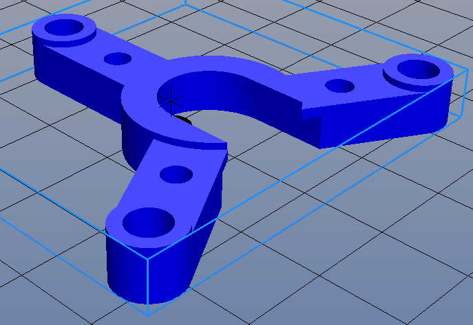
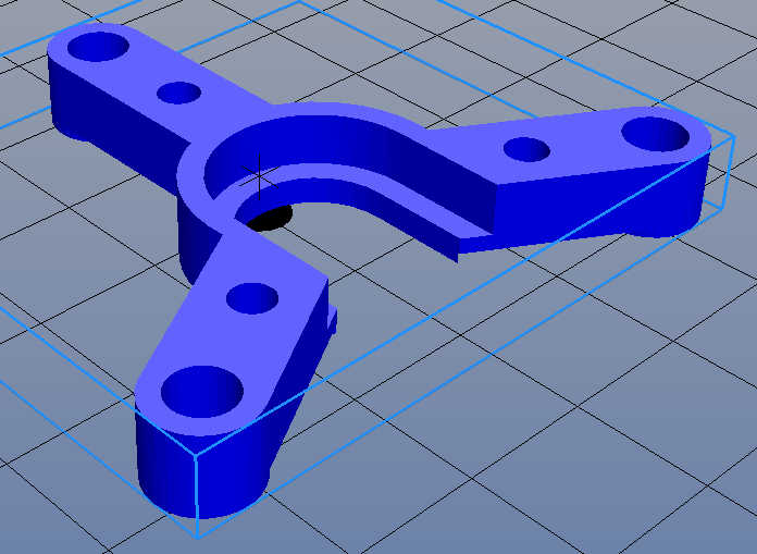
So I got a bit bored and decided to solve an issue I was having on my printer. I do a large amount of really long prints (36-52+ hours each) and I have had to replace my E3d V6 mount twice now due to it getting a TINY amount of wobble over time. It is a great designed mount, but wears out after too many large prints for my taste due to be made from plastic. So I sat down in Solidworks and throw together something that is working really great so far. Below is a picture of my BETA design and test model
 Viewed 19954 times")
It is an aluminum groove mount with a small locking ring to hold the print head in place. This rests on top of three custom length carbon fiber spacers. The spacers are capped off with ultralight weight caps that align the spacers and allow short titanium screws to replace the 1 3/4"+ steel screws and lock nut. This also allows you to only remove the mount and leave the spacers in place, thus stopping the mad juggle of trying to line up the spacer, long screw, mount, locking ring and the nut with two hands. Now you simply unscrew the nut on top and leave the screws at the bottom of the spacers attached to the printer.
So far my printing tests have shown no decreased performance compared to the mount I was using.
I am going to play with this mount for a few more days and refine it a bit more. The finish needs a bit more work to take the anodizing a bit better on the cut edges which is something I will work on in the next week or so.
I am also playing with a full carbon fiber mount to see how much weight I can lose on the print head overall. I am also planning to adapt this modular style of mount to both the Chimera and the Volcano print heads through changing spacers and the milled mount piece. Just waiting for both to arrive so I can get started on this ASAP. Also going to look at doing something very similar to the stock mount to make it a bit easier to mount a dial indicator for calibration and to lighten things up a bit on the stock print head. I had to throw it back on in a pinch while waiting for replacement parts on the E3D once. Would be nice to just undo the bottom three screws and drop in a whole unit with mount, spacers and print head with just three small screws and not fuss with the bolt/nut system.
More updates to come!
Re: Aluminum and carbon fiber E3d V6 mount.
Posted: Sun Jan 04, 2015 6:15 am
by Nareikuk
Looks great. Will there be a YellowJacket variant?

Re: Aluminum and carbon fiber E3d V6 mount.
Posted: Sun Jan 04, 2015 6:20 am
by travelphotog
I do not have access to a yellow jacket yet. I looked at it but never pulled the trigger. I am throwing around my own top board of the same style in Eagle right now. But I could easily make one to work with the yellow jacket board if I can at least get a hold of a CAD file for the board outline and such. If a few folks want them and I have the file, then it will just be a short time to turn it around.
Re: Aluminum and carbon fiber E3d V6 mount.
Posted: Sun Jan 04, 2015 6:34 am
by techstorage
Cool, looks promising.
Re: Aluminum and carbon fiber E3d V6 mount.
Posted: Sun Jan 04, 2015 7:28 am
by jesse
Looks very nice. I bet you could sell them.
Re: Aluminum and carbon fiber E3d V6 mount.
Posted: Sun Jan 04, 2015 3:41 pm
by jram
That's a beauty , nice work!
Re: Aluminum and carbon fiber E3d V6 mount.
Posted: Sun Jan 04, 2015 8:44 pm
by travelphotog
Thanks! I should have the carbon fiber plate in shortly to start milling the carbon fiber mount also. Now if my titanium screws would just hurry up and get here I could keep moving along! BTW once I have it all sorted out I am open to whipping up a few extras if there is interest. I might even but one up for grabs as a free tester once I have it all finished up. All I would ask in return is for an honest review here on the boards of the mount. But that is a bit down the road still.
Re: Aluminum and carbon fiber E3d V6 mount.
Posted: Mon Jan 05, 2015 6:54 am
by Jassper
That is sweet! (Would love to get it in Yellow

)
Would love to work with you on making it compatible with the my Quick Change hot end, I'll contact you.
EDIT
It would also be cool if you made a plate compatible with the standard SeeMe hotend, if it's not already.
Here is a simple DXF export of the
board if that will help
Re: Aluminum and carbon fiber E3d V6 mount.
Posted: Mon Jan 05, 2015 3:31 pm
by travelphotog
Jassper wrote:That is sweet! (Would love to get it in Yellow
)
Would love to work with you on making it compatible with the my Quick Change hot end, I'll contact you.
EDIT
It would also be cool if you made a plate compatible with the standard SeeMe hotend, if it's not already.
Here is a simple DXF export of the
board if that will help
Sent you a PM and looking forward to working on this.
Re: Aluminum and carbon fiber E3d V6 mount.
Posted: Mon Jan 05, 2015 3:39 pm
by travelphotog
Nareikuk wrote:Looks great. Will there be a YellowJacket variant?
I was wanting to grab some feedback from you about your thoughts on the Yellowjacket and my mount. I was looking at the Yellowjacket and noticed that overall both it and my mount serve the same purpose of mounting the print head to the effector plate. Of course the Yellowjacket packs a ton of other cool features into the same package also. I am very open to have something that would work with the Yellowjacket, but I am wondering what you had in mind? I can make a plate that will allow the Yellowjacket to be mounted on top if that is the desire, but It is sort of doubling up on attaching the head to the effector plate. I am always open to ideas and would like anyone's thoughts on how they would like the two items to work together.
M.
Re: Aluminum and carbon fiber E3d V6 mount.
Posted: Mon Jan 05, 2015 5:54 pm
by bvandiepenbos
That is a really nice looking mount.
Sturdy and lightweight. Great design.
You are right on about the long screws being a pain, I thread the OEM SeeMeCNC aluminum standoffs 8-32 and use short button head allen screws from top and bottom, then leave standoffs connected to hot end mounting plate when removing head. ...much easier!
Re: Aluminum and carbon fiber E3d V6 mount.
Posted: Mon Jan 05, 2015 6:14 pm
by travelphotog
bvandiepenbos wrote:That is a really nice looking mount.
Sturdy and lightweight. Great design.
You are right on about the long screws being a pain, I thread the OEM SeeMeCNC aluminum standoffs 8-32 and use short button head allen screws from top and bottom, then leave standoffs connected to hot end mounting plate when removing head. ...much easier!
Thanks! You beat me to the punch on your trick trucks. I still plan on getting a set and anodizing them myself down the road.. Redoing the trucks was on my to do list but you beat me to the punch. I should be picking up a set within the next month or so.
One of the main reason for my redo was to lose weight on the effector platform and make it easier to do thing like mounting a dial indicator for calibration without have to do the Rostock finger shuffle to remount everything. I went with 4-40 5/16 and 3/8 titanium button head screws for mine (still waiting for them to arrive of course). So far it is MUCH easier to switch things out. The inserts are pretty easy to mill overall for the carbon fiber tubes. I even had to mill a special tool to hold the inserts for tapping which works out really well. I do know that I will not be returning to the 3 long bolt system again. This is the way forward me so far. Have you found the screws to hold well over time? Mine have so far but I hardly have 30 hours or less on them so far in printing.
I am working on a stock head mount tonight. I should have something off the mill shortly to show everyone and get some feedback.
Re: Aluminum and carbon fiber E3d V6 mount.
Posted: Mon Jan 05, 2015 6:29 pm
by bvandiepenbos
I have not had the short standoff screws every come loose.
Re: Aluminum and carbon fiber E3d V6 mount.
Posted: Tue Jan 06, 2015 12:06 am
by travelphotog
 Viewed 19795 times")
- BETA stock SeeMeCNC hotend mount.
So this is what I am thinking right now for the stock SEEMECNC hotend mount. I should have some pics up tomorrow if the mill plays nice tonight.
Re: Aluminum and carbon fiber E3d V6 mount.
Posted: Tue Jan 06, 2015 3:37 am
by Eaglezsoar
I agree that you should put these up for sale. Hopefully you could charge enough to make a profit.
Re: Aluminum and carbon fiber E3d V6 mount.
Posted: Tue Jan 06, 2015 12:13 pm
by travelphotog
These are the fresh off the mill shots of the stock SEEMECNC hotend mount. I should get it anodized later today and also will try to cut some carbon fiber spacers and have a few shots of it mounted. Titanium screws came in today also! Really looking forward to getting everything mounted up and some beauty shots done this evening.
So here is a question for everyone. For the spacer on the stock hotend... Should we recycle the stock piece? Or would you guys like it better out of aluminum or maybe a carbon fiber tube on end as a spacer? Most votes gets to green light on that next.
Re: Aluminum and carbon fiber E3d V6 mount.
Posted: Tue Jan 06, 2015 12:20 pm
by Mac The Knife
I machined my mount out of 1/2" bar to eliminate that little melamine spacer. I had considered it part of the cause of the problem of the hot end loosening up after time.
Re: Aluminum and carbon fiber E3d V6 mount.
Posted: Tue Jan 06, 2015 2:59 pm
by travelphotog
Mac The Knife wrote:I machined my mount out of 1/2" bar to eliminate that little melamine spacer. I had considered it part of the cause of the problem of the hot end loosening up after time.
I would mill it out of 1/2 stock but for me I have two drawbacks for that on this mount. My first concern is I do not use this mount so it is a side project and the second and main concern is I only have a Shapeoko 2 CNC right now so milling that much off a 1/2" stock is just not time or cost effective. If I had a larger mill and the demand was higher I would mill from 1/2" but right now that is just not a real option for me.
I had seen your mount and saw right away that you have a nicer CNC then I have! I am looking to upgrade shortly but for now I am growing and learning on the Shapeoko.
Re: Aluminum and carbon fiber E3d V6 mount.
Posted: Tue Jan 06, 2015 3:26 pm
by Nareikuk
The yellow jacket board does not have any good way of holding the E3Dv6. There is a triangular part that can be printed to press the top of the hot end against the yellow jacket, but I think an alloy triangular wedge that clamps around the top of the hot end and bolts to the underside of the yellow jacket might be more secure. The board itself is quite thick and so will not flex very easily which is a very good start. Of course, either way, longer stand offs are required and your carbon/alloy standoff would be very nice. For mine, I printed three 13mm x 9mm diameter extensions to the aluminium standoffs supplied with the printer. I must draw up something in solid works and print it to see how it would work to hold the hot end more securely to the YellowJacket. I'll put it on my list
My explanation above could probably do with a diagram or two to help...
Re: Aluminum and carbon fiber E3d V6 mount.
Posted: Tue Jan 06, 2015 3:53 pm
by Jimustanguitar
There's no reason that you can't just use it as a connector board. There's plenty of extra JHead groove to put a different mount in there and stack the YJ on top of it.
[img]
http://i.imgur.com/Lp4xi1M.png[/img]
Re: Aluminum and carbon fiber E3d V6 mount.
Posted: Tue Jan 06, 2015 4:09 pm
by Jassper
OK, here is my idea and it addresses both issues, as pointed out that the printed tri-mount to secure a groove mount hotend isn't very good and should be Alum that screws into something solid, and second it will extend the standard 1" standoffs to allow room for the 30mm fan. I don't have fancy CAD software so I drew these in eMachine shop and exported the STL's. It also allows for either hotend, SeeMe or Groove mount.
Top view:
Shows a short standoff to support the circuit board and keep any PTH pins from shorting on the alum the over all thickness is aprox 0.25" so that on top of the 1" standoffs makes room for the 30mm fan to be mounted correctly.
[img]
http://www.themakerhive.com/FTP/jassper/hep_topview.jpg[/img]
Bottom View:
Shows a slot for groove mount type hotends. The groove mount can slide on with or without the circuit board. All the groove mounts I have have a 4.8mm groove and my board is 2.4mm, that added to the thickness in the center is aprox 4.2mm. Also the groove mounts outer most diameter is 16mm and the outer most diameter on the SeeMe is 17.8mm (unless you have a really old hotend) so the SeeMe hot end should still catch the full thickness of the alum giving us the spacing needed to tighten the center nut.
ALso, the 3 holes towards the center can be tapped 6 - 32 or M3 so an alum clamp can be screwed into place pinching everything together to hold the groove mounts into place, as suggested.
[img]
http://www.themakerhive.com/FTP/jassper/hep_botview.jpg[/img]
Clear as mud?
If your not sure you under stand, give a while and I will print one of these out and mount both a SeeMe and a Groove mount to show you what I am trying to relay.
ONe more thing, the diameter of the neck on the SeeMe hot end is 11mm while all groove mounts are 12mm, My board accommodates that difference so using this on a standard SeeMe hot end without the board may cause the hot end to be slightly off center and it could move around if not tight tight.
Re: Aluminum and carbon fiber E3d V6 mount.
Posted: Tue Jan 06, 2015 4:11 pm
by travelphotog
Hey Guys,
Jassper (maker of the Yellowjacket) has been touching base with me and I should have something out shortly that will work. I plan to seek feedback from those who have and use the Yellowjacket. I am also very open to working on custom sized spacers if anyone has an interest. I would just need the total length desired and your color choice for the end caps. I use carbon fiber tubing the same size as the stock hotend uses to makes it easier for everyone. I am by no means a CNC guru and my CNC mill has a few limits which restrict what I can do. But I look forward to feedback from everyone and hope i can produce something that will help folks out. I honestly built it to loose the single bolt system and because I just love the way it looks with the carbon fiber and such.
Re: Aluminum and carbon fiber E3d V6 mount.
Posted: Tue Jan 06, 2015 4:36 pm
by travelphotog
Jassper wrote:OK, here is my idea and it addresses both issues, as pointed out that the printed tri-mount to secure a groove mount hotend isn't very good and should be Alum that screws into something solid, and second it will extend the standard 1" standoffs to allow room for the 30mm fan. I don't have fancy CAD software so I drew these in eMachine shop and exported the STL's. It also allows for either hotend, SeeMe or Groove mount.
Top view:
Shows a short standoff to support the circuit board and keep any PTH pins from shorting on the alum the over all thickness is aprox 0.25" so that on top of the 1" standoffs makes room for the 30mm fan to be mounted correctly.
[img]
http://www.themakerhive.com/FTP/jassper/hep_topview.jpg[/img]
Bottom View:
Shows a slot for groove mount type hotends. The groove mount can slide on with or without the circuit board. All the groove mounts I have have a 4.8mm groove and my board is 2.4mm, that added to the thickness in the center is aprox 4.2mm. Also the groove mounts outer most diameter is 16mm and the outer most diameter on the SeeMe is 17.8mm (unless you have a really old hotend) so the SeeMe hot end should still catch the full thickness of the alum giving us the spacing needed to tighten the center nut.
ALso, the 3 holes towards the center can be tapped 6 - 32 or M3 so an alum clamp can be screwed into place pinching everything together to hold the groove mounts into place, as suggested.
[img]
http://www.themakerhive.com/FTP/jassper/hep_botview.jpg[/img]
I think i am following you.. I admit this would be a bit to mill on the basic CNC I use but it is not undoable, just would need a good workflow and milling to knock it out. IF you can share or PM me the STL I will throw it on the printer tonight and have something in my hands to work with. I will also be sending you the PM reply shortly. Thanks!
Clear as mud?
If your not sure you under stand, give a while and I will print one of these out and mount both a SeeMe and a Groove mount to show you what I am trying to relay.
ONe more thing, the diameter of the neck on the SeeMe hot end is 11mm while all groove mounts are 12mm, My board accommodates that difference so using this on a standard SeeMe hot end without the board may cause the hot end to be slightly off center and it could move around if not tight tight.
Re: Aluminum and carbon fiber E3d V6 mount.
Posted: Tue Jan 06, 2015 4:37 pm
by Generic Default
That thing does look pretty sweet with the CF tubes and anodized aluminum. I'm just wondering if it makes sense to use regular off the shelf aluminum spacers, since they would be so much cheaper. I need to start anodizing my own stuff. Do you do anodizing yourself or do you sent it somewhere?
Re: Aluminum and carbon fiber E3d V6 mount.
Posted: Tue Jan 06, 2015 4:59 pm
by Jassper
I just remembered something that may bring this project to a screetching halt (at least until a new board revision is done, and one is coming soon)
As it is now, the three mounting holes for the standoffs are electronically isolated, however the 3 in the middle are not. Anyone who has one of the Yellow Jacket boards look at the top of it, you will see a G- and a G+. The G- is connected to the ground and the G+ is connected to the hot end positive. This was intended to be use in conjunction with the
http://tricklaser.com/LED-hot-end-heati ... ED-HAT.htm Top Hat LED from Trick Laser. This would allow you to eliminate the wires and use the screws as conductors to power the LEDs but somewhere alone the line that didn't happen. So until that is removed from the current version of the Board, I would highly recommend using Nylon screws to secure the hotend clamp