
I noticed this first when printing a raspberry pi case.
First I tried this sleeve case: http://www.thingiverse.com/thing:604915" onclick="window.open(this.href);return false;
I found that I couldn't fit the Pi in there - I figured I'd just try a different design.
Second two-halved case: http://www.thingiverse.com/thing:665042" onclick="window.open(this.href);return false;
This had the problem of the two case halves not fitting together. Both of the cases I had printed at 0.3mm layer depth in PLA. I then tried 0.2mm layer depth and had the same problem. So I got my calipers out and started measuring! I found that my dimensions were off by between 0.15mm and 0.35mm depending on which part of the object I measured.
I did some searches on the forum and found that this can be caused by incorrect diagonal length settings. I have the U-shaped arms, and I checked my EEPROM and it is at 269mm which is apparently correct.
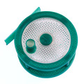
I downloaded this calibration circle - good news, my angles are perfect, but I found the following when measuring the markers. Each marker should be 60mm.
X: 59.76
Y: 59.93
Z: 59.97
So I started tweaking the diagonal length parameter in my EEPROM, printing a 100x2x2mm object to check after each change. I printed it in line with the X axis, as this was the one that was the furthest out. After getting exactly 100mm from my calibration object at a diagonal length of 258.350, I re-printed the above calibration circle. These were the new results:
X: 60.02 (+0.26)
Y: 60.19 (+0.26)
Z: 60.26 (+0.29)
So while I seem to have corrected the X axis, I've just moved the problem elsewhere. I set the diagonal rod length back to 269mm and did some more reading into how to correct problems with individual axes, and couldn't really find any concrete explanation. Thankfully 'repetier' commented on the thingiverse calibration circle with some valuable insight:
[img]http://i.imgur.com/CD9tIGD.jpg[/img]
The explanation is .. brief, and references 'Corr. diagonal A/B/C' when the EEPROM values are actually called 'Delta Radius A/B/C'. I know this because I found this forum post which references them, and thankfully found this handy 'map' of the A/B/C towers:
Code: Select all
/*  =========== Parameter essential for delta calibration ===================

            C, Y-Axis
            |                                   |___| CARRIAGE_HORIZONTAL_OFFSET
            |                                   |   \
            |_________ X-axis         |    \
           / \                                  |     \  DELTA_DIAGONAL_ROD
          /   \                                         \
         /     \                                         \    Carriage is at printer center!
         A      B                                        \_____/
                                                            |--| END_EFFECTOR_HORIZONTAL_OFFSET
                                                    |----| DELTA_RADIUS
                                                |-----------| PRINTER_RADIUS

    Column angles are measured from X-axis counterclockwise
"Standard" positions: alpha_A = 210, alpha_B = 330, alpha_C = 90Am I missing something here? Am I trying to correct this problem in the wrong way? Am I expecting too much of the printer?
Here's some photos of the raspi case compared to the STL file - the case was printed at 0.2mm layer depth. PLA. 0.4mm nozzle. Minimum 2 perimeters. Minimum 3 top / bottom layers. Perimeters 45mm/s. External Perimeters 33mm/s. Small perimeters 15mm/s. Infill 65mm/s. Hot end 195C, bed 60C. I've also attached the GCODE.
[img]http://i.imgur.com/OcwdGiY.jpg[/img]
[img]http://i.imgur.com/ht1AE63.jpg[/img]
[img]http://i.imgur.com/GV29B7M.jpg[/img]
[img]http://i.imgur.com/3uyiUVo.jpg[/img]
[img]http://i.imgur.com/abkZRyn.jpg[/img]
[img]http://i.imgur.com/WJLJ5mp.jpg[/img]
[img]http://i.imgur.com/wjMyq8e.jpg[/img]
Any guidance would be appreciated!
Thanks!