I agree with leaving the clear cover off, it's nice.
And just fyi for anyone who is strapped for cash: an easy way to get geared stepper w/flange: http://www.robotdigg.com/product/425/Fl ... mm+Stepper" onclick="window.open(this.href);return false;
Getting the most from your ezStruder
Re: Getting the most from your ezStruder
*not actually a robot
Re: Getting the most from your ezStruder
Should have posted these earlier with the others...
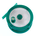
But anyways... This shows the "offsets" with the printable spacer(s) for each spool type of filament that I have. I think for the most part, according to what I've read up on, the "Spool Hubs" should work with everything out there.
This also shows why the M8 Knob (large Hershey's Kiss) is as long as it is.
Rick
- Attachments
-
- Rostock MAX v2 - Spool Support Arm - Mod RL 2x 608 - 0.5kg - SeeMeCNC
-
- Rostock MAX v2 - Spool Support Arm - Mod RL 2x 608 - 1.0kg - SeeMeCNC
-
- Rostock MAX v2 - Spool Support Arm - Mod RL 2x 608 - 1.0lbs - Taulman
My Spool Holder for the Rostock MAX v2 on Repables & Thingiverse.
Re: Getting the most from your ezStruder
OK... This is VERY important I feel.
@bvandiepenbos
@JFettig
... and everyone scratching their head!
I hooked up Brian's Fly-N-Strude, put a NEW Hobbed Gear onto the NEMA 17 (stock) Stepper Motor, did the EZStruder "mods" that Brian pointed out and everything is flawless!
Have Trick Laser 300mm Carbon Fiber Arms too.
However... And this is a BIG however!
The machine is so "tight" now that it is EASY to see the "Vertical Banding" caused by the Stepper Motor "pulses". We both couldn't believe it (friend of mine AEK on here). I mentioned that it was probably caused from the pulses from the stepper motor, so he reached up and touched the Stepper Motor manual filament knob and sure enough, it was pulsing exactly the same as the visual vertical banding that we were getting!
So this PROVES that a Geared Stepper Motor is needed in "tight" machines if you want to eliminate any artifact(s) caused from the pulses coming from the stepper motor. We even speeded up the print speed all the way from 25mm/s to 250mm/s yet the artifacts remained, albeit not quite as visible, yet still there.
Below I've attached some photo's of the "vertical banding".
I think that this information should be put out there for everyone to know. Was VERY surprised to see this!
- Attachments
-
- NEMA 17 Vertical Banding - 01
-
- NEMA 17 Vertical Banding - 02
My Spool Holder for the Rostock MAX v2 on Repables & Thingiverse.

Re: Getting the most from your ezStruder
Rather large topic regarding vertical banding, but I don't think it's related to the extruder (bowden) as multiple machines including Cartesian printers have that issue as-well.
http://forum.seemecnc.com/viewtopic.php ... al+banding" onclick="window.open(this.href);return false;
http://forum.seemecnc.com/viewtopic.php ... al+banding" onclick="window.open(this.href);return false;
Re: Getting the most from your ezStruder
All, the stock ezStruder and RAMBo configured for 16 microsteps gives you what, something like 90 steps/mm? Increasing the # of microsteps to get better stepper resolution has a BIG down side - significantly reduced torque. And an extruder needs lots of torque to push that filament. I noticed this quietly clearly when I had my Azteeg X3 Pro configured for 32 microsteps to try to get the resolution higher. No doubt, the banding decreased but the pulsing of the stepper was even more pronounced. In fact, I noticed this just as I was starting to print with the CF PLA filaments earlier this year. These are very viscous and do not flow or string like normal PLA. You also have to print much slower. So I slowed down to about 20mm/s for my first layer and was surprised to see not a continuous bead of filament but rows of little dots! Like the extruder had become a microscopic Hershey Kiss maker! Counterintuitively, when I sped up to about 35 mm/s the dots disappeared and a line of filament was deposited. However, I could see the pulses in these lines under a magnifier.
This ultimately led to doing some research and the "common wisdom" seems to be that an extruder should be a minimum of 400 steps/mm to work well. This is likely why there were so many geared extruders in the early days and then the direct drives came on the market to reduce complexity and size/mass. Unfortunately, they are right at the minimum end of steps/mm to function and difficult/viscous materials expose the problem clearly. I then decided to go the 5.18:1 geared stepper route on the ezStruder as per the mod in this thread. I have not looked back! 5.18 * 90 > 400 steps/mm, well within the "good" range. Not only did my success at printing CF PLA go way up but the banding issue is negligible. I've converted all 5 of my printers to geared stepper motor ezStruders and haven't looked back.
One thing you might try to see if this is what's causing your banding is to change the microsteps for your extruder and the steps/mm and see if this has an effect on the banding pattern. It did for me. With the X3 Pro I could try 8, 16 and 32 microsteps and print the same part from the same gcode and see 3 very different banding patterns. Not terribly scientific but clear enough to prompt me to move to geared steppers. There are many factors that contribute to this so it is complicated. Smaller orifices create more back pressure requiring more torque... More viscous filaments do the same. Even the color of the filament can hide or really highlight the banding. And of course the delta motion control can contribute. But, at the end of the day, the low steps/mm with a direct drive extruder seemed to be a logical problem area. It may not fix every problem but I'd like to see some others before and after prints using the exact same gcode and printer config (except the geared stepper motor) before and after the conversion.
Sublime Layers - my blog on Musings and Experiments in 3D Printing Technology and Art
Start Here:
A Strategy for Successful (and Great) Prints
Strategies for Resolving Print Artifacts
The Eclectic Angler
Re: Getting the most from your ezStruder
@KAS
Thanks for the Thread Post.
@mhackney
Yes, I concluded the exact same thinking. The "tighter" these machines become via. upgrades to eliminate backlash, etc... The more prominent other "errors" appear.
I've ordered the 5.2:1 Geared Stepper from within this Thread.
Once it arrives and it's mounted, I'll run the EXACT same G-Code through the printer and post the results.
My Spool Holder for the Rostock MAX v2 on Repables & Thingiverse.
-
bvandiepenbos

- Printmaster!
- Posts: 927
- Joined: Thu Apr 05, 2012 11:25 pm
- Location: Goshen, IN
- Contact:
Re: Getting the most from your ezStruder
I have a 99:1 geared nema 17 left over from another project... I have been wanting to try it for a extruder with a large (50mm dia.) custom made hob.
My thinking is better grip due to large hob. But now maybe additional benefit would be smoother motor stepping since gear ratio is so high.
What do you all think?
Worth a try?
My thinking is better grip due to large hob. But now maybe additional benefit would be smoother motor stepping since gear ratio is so high.
What do you all think?
Worth a try?
~*Brian V.
RostockMAX v2 (Stock)
MAX METAL "ShortyMAX"
MAX METAL Rostock MAX Printer Frame
NEMESIS Air Delta v1 & v2 -Aluminum delta printers
Rostock MAX "KITT" - Tri-Force Frame
GRABER i3 "Slim"
RostockMAX v2 (Stock)
MAX METAL "ShortyMAX"
MAX METAL Rostock MAX Printer Frame
NEMESIS Air Delta v1 & v2 -Aluminum delta printers
Rostock MAX "KITT" - Tri-Force Frame
GRABER i3 "Slim"
-
Renha

- Printmaster!
- Posts: 282
- Joined: Fri Apr 11, 2014 2:18 am
- Location: Balashikha, Russian Federation
- Contact:
Re: Getting the most from your ezStruder
bvandiepenbos, great idea, I think it should work!
3D printing is magic!
Sorry my engrish :-/ you could PM me in Russian.
Sorry my engrish :-/ you could PM me in Russian.
Re: Getting the most from your ezStruder
Brian, I think a scientifically designed experiment is necessary. A double blind test. So, the best way to proceed would be for me to duplicate your environment. So, please send me a MAX METAL kit, CF tube arms, MAX METAL Platform, the Trick Trucks of course and any other bits I'll need to replicate your setup. I'll assemble and outfit with a 99:1 nema 17 and we can run a double blind test.  I need another printer soon.
Cheers,
Michael
Cheers,
Michael
Sublime Layers - my blog on Musings and Experiments in 3D Printing Technology and Art
Start Here:
A Strategy for Successful (and Great) Prints
Strategies for Resolving Print Artifacts
The Eclectic Angler
Re: Getting the most from your ezStruder
Yea, I pretty much tossed coin at just about anything to fix that vertical banding issue and stopped once I changed the three tower steppers to 400 step/rev with 16t pulleys. That made a huge change in quality and decided not to pursue anything else and enjoy the printer for what it is. I've been running the stock ezStruder and stepper since day one, although that will change soon as curiosity is getting the better of me.
Back part of the above screw driver holder. Still has the vertical banding, just not as bad as it use to be. Printed with 3 perimeters at .20 layers, PLA
Back part of the above screw driver holder. Still has the vertical banding, just not as bad as it use to be. Printed with 3 perimeters at .20 layers, PLA
-
bvandiepenbos
- Printmaster!
- Posts: 927
- Joined: Thu Apr 05, 2012 11:25 pm
- Location: Goshen, IN
- Contact:
Re: Getting the most from your ezStruder
your so kindmhackney wrote:Brian, I think a scientifically designed experiment is necessary. A double blind test. So, the best way to proceed would be for me to duplicate your environment. So, please send me a MAX METAL kit, CF tube arms, MAX METAL Platform, the Trick Trucks of course and any other bits I'll need to replicate your setup. I'll assemble and outfit with a 99:1 nema 17 and we can run a double blind test.
Cheers,
Michael
~*Brian V.
RostockMAX v2 (Stock)
MAX METAL "ShortyMAX"
MAX METAL Rostock MAX Printer Frame
NEMESIS Air Delta v1 & v2 -Aluminum delta printers
Rostock MAX "KITT" - Tri-Force Frame
GRABER i3 "Slim"
RostockMAX v2 (Stock)
MAX METAL "ShortyMAX"
MAX METAL Rostock MAX Printer Frame
NEMESIS Air Delta v1 & v2 -Aluminum delta printers
Rostock MAX "KITT" - Tri-Force Frame
GRABER i3 "Slim"
Re: Getting the most from your ezStruder
I am! I think you have my mailing address on file but in the spirit of kindness, I'm happy to email it to you.
Sublime Layers - my blog on Musings and Experiments in 3D Printing Technology and Art
Start Here:
A Strategy for Successful (and Great) Prints
Strategies for Resolving Print Artifacts
The Eclectic Angler
Re: Getting the most from your ezStruder
bvandiepenbos wrote:I have a 99:1 geared nema 17 left over from another project... I have been wanting to try it for a extruder with a large (50mm dia.) custom made hob.
My thinking is better grip due to large hob. But now maybe additional benefit would be smoother motor stepping since gear ratio is so high.
What do you all think?
Worth a try?
Brian,
we should do the math on it to see if it would make sense, 50mm is ~4.166 times larger circumferential, so you're still around 25:1 with a standard drive gear.
I designed some line control equipment about 5 years back where we were holding incredible tolerances, we originally sized our motors and gearboxes very reasonably and later ended up with very high ratios to keep the motors spinning faster and we got better control, slow speeds were giving us some issues.
The downside to going more than 5:1 is that your retract and rapid speeds will be very slow.
Re: Getting the most from your ezStruder
+1 JFettig, that is the tradeoff with going high gear ratio - sacrifice speed and it can limit your top end print speed significantly. That's why the 400 step/mm target is a good compromise. It allows for fast printing while providing a smooth drive and good torque. Now I've probably ruined my chance to get that MAX METAL setup .
Sublime Layers - my blog on Musings and Experiments in 3D Printing Technology and Art
Start Here:
A Strategy for Successful (and Great) Prints
Strategies for Resolving Print Artifacts
The Eclectic Angler
-
bvandiepenbos
- Printmaster!
- Posts: 927
- Joined: Thu Apr 05, 2012 11:25 pm
- Location: Goshen, IN
- Contact:
Re: Getting the most from your ezStruder
yes, but it still may be fast enough? I would probably FULL step instead of 16 micro steps, that would help.JFettig wrote:bvandiepenbos wrote:I have a 99:1 geared nema 17 left over from another project... I have been wanting to try it for a extruder with a large (50mm dia.) custom made hob.
My thinking is better grip due to large hob. But now maybe additional benefit would be smoother motor stepping since gear ratio is so high.
What do you all think?
Worth a try?
Brian,
we should do the math on it to see if it would make sense, 50mm is ~4.166 times larger circumferential, so you're still around 25:1 with a standard drive gear.
I designed some line control equipment about 5 years back where we were holding incredible tolerances, we originally sized our motors and gearboxes very reasonably and later ended up with very high ratios to keep the motors spinning faster and we got better control, slow speeds were giving us some issues.
The downside to going more than 5:1 is that your retract and rapid speeds will be very slow.
The math eludes me at the moment, what would my steps/MM be with the following?...
- 200 step motor, full stepping
- Motor gearbox ratio 99:1
- Drive hob 50 mm diameter
anyone know how fast you can spin the motor with Rambo board?
~*Brian V.
RostockMAX v2 (Stock)
MAX METAL "ShortyMAX"
MAX METAL Rostock MAX Printer Frame
NEMESIS Air Delta v1 & v2 -Aluminum delta printers
Rostock MAX "KITT" - Tri-Force Frame
GRABER i3 "Slim"
RostockMAX v2 (Stock)
MAX METAL "ShortyMAX"
MAX METAL Rostock MAX Printer Frame
NEMESIS Air Delta v1 & v2 -Aluminum delta printers
Rostock MAX "KITT" - Tri-Force Frame
GRABER i3 "Slim"
Re: Getting the most from your ezStruder
Brian, the formula is:
(stepper steps per revolution * number of micro steps) / (Pi * diameter of driver gear in mm)
For the stock ezStruder:
(200 steps per revolution * 16 microsteps) / (Pi * 12mm) (note: I chose 12mm for the drive gear for simplicity, it is a little different)
So, 80.2 steps/mm
With a geared stepper you multiply the numerator (stepper steps per revolution * number of microsteps) by the gear ration. So in the eZStruder case with a 5.18:1 gear ratio:
(200 steps per revolution * 16 microsteps * 5.18) / (Pi * 12mm) = 415.5 steps/mm
Sublime Layers - my blog on Musings and Experiments in 3D Printing Technology and Art
Start Here:
A Strategy for Successful (and Great) Prints
Strategies for Resolving Print Artifacts
The Eclectic Angler
Re: Getting the most from your ezStruder
Received my NEMA 17 Geared Stepper Motor Mounts from JFettig (thank you again!) and I'm getting ready to mount it all up (two machines).
However, once we pulled out the RAMBO board to put in the Smoothieboard, we looked at the "current" settings for the stock Rostock MAX v2 stepper motors.
They were set to: #define MOTOR_CURRENT {155,155,155,165,0} where a value of ~185 = 1.0A making this setup equal to ~0.84A, 0.84A, 0.84A, 0.89A
Were they really to be set that low?
Considering that the "specs" say 1.5A and some resources say 1.2A for NEMA 17's.
What are you guys setting your XYZ stepper motors to?
Also, the Geared Kysan I picked up states it's current is 1.0A with a voltage of 2.4v (same one JFettig is using).
I'm confused now!
What should the stock motors on a RMAXv2 be set to and the Geared Stepper mentioned be set to in Smoothie?
My Spool Holder for the Rostock MAX v2 on Repables & Thingiverse.
Re: Getting the most from your ezStruder
Set it to 1 a then see how it goes. That is where I have mine set on 24v and smoothie
Re: Getting the most from your ezStruder
The Extruder Geared Stepper I'll set to 1.0A.
But what about the XYZ Steppers?
But what about the XYZ Steppers?
My Spool Holder for the Rostock MAX v2 on Repables & Thingiverse.
Re: Getting the most from your ezStruder
I think the motors have nameplates with current ratings. Start there then see if they get hot or not
-
EskimoRuler
- Plasticator
- Posts: 14
- Joined: Mon Feb 09, 2015 2:38 am
Re: Getting the most from your ezStruder
Hey JFettig, just wanted to give you a shout out on your adapter plates. Already lovin' it and haven't even printed with it yet.JFettig wrote:I got to play with my new Haas a little today and whipped up a couple of these plates to adapt the gear motor to the EZStruder. I designed it to use the 8mm Tridprinting hobbed drive gear with the Kysan gear motor they have listed. The plate has to be that thick to center the hobbed section on the path of the filament with it oriented with the screw in back since this gear is slightly larger than stock.
If anyone has any interest in these I can do a small run of these.
[img]http://i.imgur.com/qsqtMBJ.jpg[/img]
[img]http://i.imgur.com/PowKU74.jpg[/img]
[img]http://i.imgur.com/ormPHgP.jpg[/img]
[img]http://i.imgur.com/WBdJtDr.jpg[/img]
[img]http://i.imgur.com/hE4gMdi.jpg[/img]
Hobbed gear: http://www.tridprinting.com/Mechanical- ... Drive-Gear" onclick="window.open(this.href);return false;
Geared Kysan: http://www.tridprinting.com/Electronics/" onclick="window.open(this.href);return false;
It should work with any Nema 17 gear motor with the same physical dims as the Kysan
Thanks Brian for these suggestions on upgrading the ezstruder, I can already tell that these mods should help out.
I plan on printing out some PTC Locks for the bowden couplers, but for now, a bent paperclip works great, PTFE Tube doesn't move at all.
Just started mounting everything last night.
I bought a Phidgets Geared stepper
http://www.phidgets.com/products.php?product_id=3325
a hobbled gear from Maker's Tool Works
http://store.makerstoolworks.com/extrud ... -8mm-bore/
a couple Bowden couplers and some PTFE Tubing from Distech
http://www.dta-labs.com/products/bowden-coupler
http://www.dta-labs.com/products/ptfe-tubing-100mm
Re: Getting the most from your ezStruder
I've been researching, designing, testing, "repeat" a new gear motor driven extruder and in the process have studied the ezStruder everywhichway. I get reports (and many posts here) of ezStruder skipping issues and filament starving. With every thing else in order I can say that the week link in the ezStruder is the spring. Simply doing Brian's M4x10 spring shim enhancement is the best single thing you can do to the ezStruder.
Funny story related to this and what got me not the trail:
I've been printing PLA (my fly reels) for over a year without a single issue - no skipping, no starving, just beautiful prints. I have it down to an art. Recently I printed a bunch of parts in carbon fiber PLA. After I was done I decided to tear down my extruder to make some measurements and perhaps clean the cog. I put it back together and ever since I've had intermittent filament starving and skipped steps. It was driving me crazy and I knew everything about my printer was in good order - the only change was tearing down and cleaning the extruder. Guess what? I forgot to re-install the M4 screw. So during a print that was less than perfect due to filament starving I paused the printer and inserted an M4 screw and restarted. The print finished with NO additional starving and I haven't had a problem since.
Perhaps the springs weaken or there is manufacturing variability in them but the extra force that the M4 screw mod provides is just enough to make it work very reliably. YMMV but give it a try.
Sublime Layers - my blog on Musings and Experiments in 3D Printing Technology and Art
Start Here:
A Strategy for Successful (and Great) Prints
Strategies for Resolving Print Artifacts
The Eclectic Angler
Re: Getting the most from your ezStruder
I second the "bolt in spring" upgrade for the EZStruder from Brian.
We did a test print a few days ago running PLA through a Geared Stepper Motor & EZStruder on a Fly-n-Strude mount...
We pushed to SmoothieBoard up to 500% and the Hotend could barely keep up with the temps... Yet, the extruder kept on pushing the filament through without skipping a beat what so ever!
The 500% push yielded an almost super flat matt black (way to cold).
But I can't stress enough how much a difference it makes to run a Geared Stepper Motor, with a "bolt in spring" setup. Works perfect!
The Fly-n-Strude IMO makes things that much better.
My Spool Holder for the Rostock MAX v2 on Repables & Thingiverse.
Re: Getting the most from your ezStruder
OK I have now uploaded to Repables & Thingiverse the "Rostock MAX v2 - Spool Support Arm - Mod RL 2x 608" that I had posted earlier in this thread.
It can be found here on Repables:
http://repables.com/r/623" onclick="window.open(this.href);return false;
It can be found here on Thingiverse:
http://www.thingiverse.com/thing:1060029" onclick="window.open(this.href);return false;
So for those that were looking for and asking for these files, they are now online for you to enjoy!
Cheers!
My Spool Holder for the Rostock MAX v2 on Repables & Thingiverse.
Re: Getting the most from your ezStruder
Well, myself and AEK on the forums here have the Geared Stepper Motor installed on a Fly-n-Strude running off of a SmoothieBoard on a Rostock MAX v2.
We will be installing the 0.9 Degree Steppers with 16 Tooth Pulleys next, but in the meantime, the vertical banding is almost non existent!
The following prints were done at 0.300mm layer heights at 80mm/sec "default" print speed in Simplify3D on a stock Rostock MAX v2 Hotend/Nozzle.
PLA: Nozzle @ 205, Bed @ 55 with no glue (bare glass).
Looking very good so far!
FSR's mounted under the bed on custom machined mounts I made.
We will be installing the 0.9 Degree Steppers with 16 Tooth Pulleys next, but in the meantime, the vertical banding is almost non existent!
The following prints were done at 0.300mm layer heights at 80mm/sec "default" print speed in Simplify3D on a stock Rostock MAX v2 Hotend/Nozzle.
PLA: Nozzle @ 205, Bed @ 55 with no glue (bare glass).
- GreenHouse Rod Supports - 01
- GreenHouse Rod Supports - 02
- GreenHouse Rod Supports - 03
- GreenHouse Rod Supports - 04
FSR's mounted under the bed on custom machined mounts I made.
My Spool Holder for the Rostock MAX v2 on Repables & Thingiverse.