Interfacing to the new HE280 accelerometer...

A place to talk about user-made mods and upgrades to their machines
User avatar
mhackney
ULTIMATE 3D JEDI
Posts: 5412
Joined: Mon Mar 26, 2012 4:15 pm
Location: MA, USA
Contact:

Interfacing to the new HE280 accelerometer...

Post by mhackney »

Background: the accelerometer probe currently talks to RAMBo via I2C and the probe "hit" is triggered via an interrupt to the RAMBo. All of the control logic is implemented in firmware (Repetier) on RAMBo. This means that supporting the new HE280/probe on other controllers and firmware (need I say it, Duet and dc42) will require coding unique to the probe. So, I had an idea to do the control logic in a small processor and have it relay the "hit" signal as a binary output to the controller - in essence, mimicking the way a simple mechanical switch works. This is basically how the JohnSL works with FSRs too.

I'm doing a proof of concept with an Arduino Micro and a spare HE280 PCB I bought. I also have an MMA845X accelerometer board I experimented last year with that I know I can talk to and get data from.

I documented the HE280 PCB pins and mapped what I think are the bare essentials:

1 -> Fan 0 GND (orange)
2 -> Heat 0 +12V (red) RED +12VDC
3 -> Heat 0 -12V (black)
4 -> T0 GND (white) BLACK GND
5 -> I2C SCL outside (black) GREEN
6 -> I2C SDA inside (red) YELLOW
7 -> PS-ON (INT) GND (blue) BLUE
8 -> TO + (green)

the colors in the right column are for my wiring to the Arduino. So I have 12V+ and GND (red and black) and SCL is green and SDA is yellow and the interrupt line is blue. I am powering the PCB with a 12V wallwart and the Arduino with its USB connection.
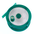
This photo is basically to document the connection to the PCB:
IMG_6788.JPG
This shows the 3 wires (SCL/SCA and interrupt) to the Arduino Micro:
IMG_6787.JPG
To test, I am using an open source I2C scanner sketch that simply scans the I2C bus looking for slave devices - this is to keep it simple for now (and because when I originally tried to test my code I ran into problems - hence the reason for this post!). When I run this scanner it does not find the probe. In fact, the scanner code hangs on the first call to read a register. I'll spare my debugging details but it I hook up the MMA845X accelerometer, the scanner finds it on the bus. Now, if I hook up both accelerometers (this is actually shown in the photo above but you don't see the MMA845X off the bottom of the photo) the MMA845X is found but the PCB is not and it does not hang. I have tried pull up resisters (4k7 to 5V) as I found that the "Wire" library can hang if the SCL and SDA lines stay low and the pull-ups keep them high. But this does not work.

So I'm left scratching my head! It is possible that I don't understand the connection requirements to the PCB. For instance, maybe pin 1 (Fan 0) needs to be connected and/or Heat 0 (pin 3) too or the thermistor?

I'm sure if I can talk to it I can get it to do my bidding!

Sublime Layers - my blog on Musings and Experiments in 3D Printing Technology and Art

Start Here:
A Strategy for Successful (and Great) Prints

Strategies for Resolving Print Artifacts

The Eclectic Angler
Eric
Printmaster!
Posts: 726
Joined: Sat Aug 18, 2012 4:09 am
Location: Chula Vista, CA

Re: Interfacing to the new HE280 accelerometer...

Post by Eric »

You haven't connected your HE280 ground to the Arduino ground. I2C requires a common ground to function.
User avatar
mhackney
ULTIMATE 3D JEDI
Posts: 5412
Joined: Mon Mar 26, 2012 4:15 pm
Location: MA, USA
Contact:

Re: Interfacing to the new HE280 accelerometer...

Post by mhackney »

Thanks Eric, what would that look like in the photo? Simply connect the GND at the upper right to the brown GND on the Arduino at the lower left - the yellow circles:
?
IMG_6787.JPG

Sublime Layers - my blog on Musings and Experiments in 3D Printing Technology and Art

Start Here:
A Strategy for Successful (and Great) Prints

Strategies for Resolving Print Artifacts

The Eclectic Angler
User avatar
mhackney
ULTIMATE 3D JEDI
Posts: 5412
Joined: Mon Mar 26, 2012 4:15 pm
Location: MA, USA
Contact:

Re: Interfacing to the new HE280 accelerometer...

Post by mhackney »

That makes sense in that the MMA845X is being powered off the 5VDC / GND supplied by the Arduino - the brown and red wires at the lower left of the breadboard.

Sublime Layers - my blog on Musings and Experiments in 3D Printing Technology and Art

Start Here:
A Strategy for Successful (and Great) Prints

Strategies for Resolving Print Artifacts

The Eclectic Angler
User avatar
mhackney
ULTIMATE 3D JEDI
Posts: 5412
Joined: Mon Mar 26, 2012 4:15 pm
Location: MA, USA
Contact:

Re: Interfacing to the new HE280 accelerometer...

Post by mhackney »

I suppose the easiest thing might be to power the Arduino Micro from the save 12V wall wart.

Sublime Layers - my blog on Musings and Experiments in 3D Printing Technology and Art

Start Here:
A Strategy for Successful (and Great) Prints

Strategies for Resolving Print Artifacts

The Eclectic Angler
Eric
Printmaster!
Posts: 726
Joined: Sat Aug 18, 2012 4:09 am
Location: Chula Vista, CA

Re: Interfacing to the new HE280 accelerometer...

Post by Eric »

Yup, that would do it. Connecting any arduino ground pin to the ground bus line should get you better results.
Connecting VIN to the +12V bus would mean USB power is no longer required. Of course you still need USB for other reasons.
User avatar
mhackney
ULTIMATE 3D JEDI
Posts: 5412
Joined: Mon Mar 26, 2012 4:15 pm
Location: MA, USA
Contact:

Re: Interfacing to the new HE280 accelerometer...

Post by mhackney »

Well, now the scanner code does not hang and reports "no devices found." So I installed pull ups and tried again and now the arduino won't show up. I reset and even connected it to a different PC and get port not found errors. So I reverted back to just the arduino on USB with no other connections and still can not see it. ugh

Sublime Layers - my blog on Musings and Experiments in 3D Printing Technology and Art

Start Here:
A Strategy for Successful (and Great) Prints

Strategies for Resolving Print Artifacts

The Eclectic Angler
Eric
Printmaster!
Posts: 726
Joined: Sat Aug 18, 2012 4:09 am
Location: Chula Vista, CA

Re: Interfacing to the new HE280 accelerometer...

Post by Eric »

Try one device at a time on the i2c bus before you worry about multiple devices on the bus.
And make sure you don't have the clock and data lines swapped (I dont remember which arduino pin is which).
User avatar
mhackney
ULTIMATE 3D JEDI
Posts: 5412
Joined: Mon Mar 26, 2012 4:15 pm
Location: MA, USA
Contact:

Re: Interfacing to the new HE280 accelerometer...

Post by mhackney »

Yes, I removed the other device and kept it simple. I have verified clock and data multiple times and the MMA845X worked so I am confident I have them identified. I think I blew the arduino connecting things with it powered on 12V. It just won't come up. I do hear the windows "bumb bomb" when I plug it in but get a no COM port found.

Sublime Layers - my blog on Musings and Experiments in 3D Printing Technology and Art

Start Here:
A Strategy for Successful (and Great) Prints

Strategies for Resolving Print Artifacts

The Eclectic Angler
User avatar
mhackney
ULTIMATE 3D JEDI
Posts: 5412
Joined: Mon Mar 26, 2012 4:15 pm
Location: MA, USA
Contact:

Re: Interfacing to the new HE280 accelerometer...

Post by mhackney »

Does anyone know if the Arduino Nano can support simultaneous USB and I2C communication? This is the primary reason I got the Micro. Last year I was working with the ATTTiny85 and it can not communicate over I2C and USB simultaneously so it made it very difficult to debug (i.e. could not spit out debugging info to the console). It looks like the Nano can support both as I don't see a disclaimer on http://www.arduino.org/products/boards/arduino-nano

Sublime Layers - my blog on Musings and Experiments in 3D Printing Technology and Art

Start Here:
A Strategy for Successful (and Great) Prints

Strategies for Resolving Print Artifacts

The Eclectic Angler
Eric
Printmaster!
Posts: 726
Joined: Sat Aug 18, 2012 4:09 am
Location: Chula Vista, CA

Re: Interfacing to the new HE280 accelerometer...

Post by Eric »

The Tiny85 has like 5 pins to work with...gotta be compromises on features with that restriction.

Functionally the Micro and Nano are close to the same thing. The Micro has a newer cpu with integrated usb, while the nano has an onboard usb to serial chip that talks to the cpu's serial port. You may have to load a different USB driver to support it, depending on which usb chip is used. After that, it'll work the same.

I usually use Pro Mini's in my own little projects, which is basically a Nano without the integrated USB interface. Instead, I use a separate USB to serial adapter to get full functionality during development. Most of the time I have no need for USB in the finished project, so that works out well. And the serial header is still there if I need to make an update.

I've recently started playing with an esp8266, which is most obviously a wifi module. It's also got a bunch of multi-purpose gpio pins and a pretty capable little cpu. But that's another story.
duvdev
Printmaster!
Posts: 167
Joined: Wed Aug 13, 2014 5:23 am

Re: Interfacing to the new HE280 accelerometer...

Post by duvdev »

Nice. Looks good.
BTW, mhackney I sent you a PM.
morgandc
Printmaster!
Posts: 280
Joined: Mon Sep 26, 2016 8:32 pm

Re: Interfacing to the new HE280 accelerometer...

Post by morgandc »

Very cool plan...hopefully seemecnc is working on something similar...
User avatar
mhackney
ULTIMATE 3D JEDI
Posts: 5412
Joined: Mon Mar 26, 2012 4:15 pm
Location: MA, USA
Contact:

Re: Interfacing to the new HE280 accelerometer...

Post by mhackney »

They are not to my knowledge and I've been talking to them about this. They have a solution that works for their printer and controller. They've been pretty good about creating an ecosystem for companies/products to support their platform with upgrades.

Sublime Layers - my blog on Musings and Experiments in 3D Printing Technology and Art

Start Here:
A Strategy for Successful (and Great) Prints

Strategies for Resolving Print Artifacts

The Eclectic Angler
User avatar
mhackney
ULTIMATE 3D JEDI
Posts: 5412
Joined: Mon Mar 26, 2012 4:15 pm
Location: MA, USA
Contact:

Re: Interfacing to the new HE280 accelerometer...

Post by mhackney »

I got 2 new Arduino Micros yesterday so I could pick up this project again. The idea was to power the Arduino and the HE280 PCB from the same 12VDC supply to maintain a common ground. One of the boards was DOA. The other one worked long enough for me upload my sketch and then apparently fried. These were not official Arduino Micros - I ordered them because I could get 2 day delivery on Amazon. The Micro is supposed to accept a 6-20V input (with 7-12V) preferred. But this one couldn't handle 12V and I suspect my official Arduino Micro that gave up the ghost a few posts back suffered from the same problem. I did measure the output voltage on my supply and it is 12V.

I have a new official Arduino Micro arriving today. But I need to figure out how to power it with a common ground with the HE280 PCB without blowing this one!

Sublime Layers - my blog on Musings and Experiments in 3D Printing Technology and Art

Start Here:
A Strategy for Successful (and Great) Prints

Strategies for Resolving Print Artifacts

The Eclectic Angler
Eric
Printmaster!
Posts: 726
Joined: Sat Aug 18, 2012 4:09 am
Location: Chula Vista, CA

Re: Interfacing to the new HE280 accelerometer...

Post by Eric »

Given your experience so far, I'd look for a better power supply than that wall-wart. It may measure 12V, but it's probably dirty unregulated power. The nano/micro boards don't mount big capacitors like the full-size boards...they assume the input power is pretty clean to start with.

Forget the 20V input number, even if it's technically true for genuine Arduinos. Most arduino clones use the AMS1117 voltage regulator, which has a max input of 15V and is generally not used above 12V.

If you're only using the HE280 for the accelerometer, you can feed it less than 12V if you want. Anything down to 7V will likely still work, since all it does with that power is change it into 5V and 3.3V. The power LED will dim as you turn down the voltage is all.
User avatar
mhackney
ULTIMATE 3D JEDI
Posts: 5412
Joined: Mon Mar 26, 2012 4:15 pm
Location: MA, USA
Contact:

Re: Interfacing to the new HE280 accelerometer...

Post by mhackney »

Thanks Eric. I have a couple of good 12VDC bench top lab power supplies. I can use one of those and I'll likely step down to 9V for the Arduino.

I am only using the accelerometer on the HE280 at this point for the proof of concept so I could power it and the Micro off 9V.

Sublime Layers - my blog on Musings and Experiments in 3D Printing Technology and Art

Start Here:
A Strategy for Successful (and Great) Prints

Strategies for Resolving Print Artifacts

The Eclectic Angler
User avatar
mhackney
ULTIMATE 3D JEDI
Posts: 5412
Joined: Mon Mar 26, 2012 4:15 pm
Location: MA, USA
Contact:

Re: Interfacing to the new HE280 accelerometer...

Post by mhackney »

Ok, I'm still scratching my head on this...

I have a new Arduino Micro. I also got an adjustable DC-DC Buck that I set to 9VDC output. I then flashed the Arduino with an I2C scanner sketch (which I got on the web and is known to work). I hooked everything up so now I am powering the Arduino and PCB from the same 9VDC supply with common ground, I am not seeing the accelerometer. I hook up a little barometric pressure and temperature probe and it shows up immediately.

I know I have the correct SDA and SCL terminals on the PCB but just to be sure I swapped them. Still no device. I see on the PCB schematic that it has pull-ups on board for these lines. I'm at a loss about where to go next. I have the code written but can't test it. And just to restate, here are the PCB connections and how I am using them. For this test, the PS-ON (blue) is not hooked up.

Code: Select all

1 -> Fan 0 GND (orange)
2 -> Heat 0 +12V (red)                  RED +12VDC
3 -> Heat 0 -12V (black)					
4 -> T0 GND (white)                     BLACK GND
5 -> I2C SCL outside (black)            GREEN
6 -> I2C SDA inside (red)               YELLOW
7 -> PS-ON (INT) GND (blue)             BLUE
8 -> TO + (green)

Sublime Layers - my blog on Musings and Experiments in 3D Printing Technology and Art

Start Here:
A Strategy for Successful (and Great) Prints

Strategies for Resolving Print Artifacts

The Eclectic Angler
User avatar
mhackney
ULTIMATE 3D JEDI
Posts: 5412
Joined: Mon Mar 26, 2012 4:15 pm
Location: MA, USA
Contact:

Re: Interfacing to the new HE280 accelerometer...

Post by mhackney »

I should add, the PCB blue (2) LEDs do illuminate. Perhaps I need to connect pin 3 and or 1?

Sublime Layers - my blog on Musings and Experiments in 3D Printing Technology and Art

Start Here:
A Strategy for Successful (and Great) Prints

Strategies for Resolving Print Artifacts

The Eclectic Angler
Eric
Printmaster!
Posts: 726
Joined: Sat Aug 18, 2012 4:09 am
Location: Chula Vista, CA

Re: Interfacing to the new HE280 accelerometer...

Post by Eric »

If it were me, I'd first check the HE280 voltage regulators to see if they are indeed producing 3.3V and 5V as expected. I'm looking at this schematic and pcb layout:
https://github.com/seemecnc/Machine_Ele ... CB_v5d.PDF

After that you might consider trying that HE280 in a known-good environment to see if it is still a working device. I think simply plugging it into the wire harness of your V3 near the hot end and seeing if probe commands worked should accomplish that. No need to disassemble anything, just make sure don't short anything on metal parts as it dangles (put masking tape on things if needed). You could even simulate probe hits by flicking it with your thumb, assuming you get that far.

Assuming all that worked, then I'd probably hook up a logic analyzer to see what's actually happening with the data lines in the working and non-working cases. Odds are you aren't set up to do that.
User avatar
mhackney
ULTIMATE 3D JEDI
Posts: 5412
Joined: Mon Mar 26, 2012 4:15 pm
Location: MA, USA
Contact:

Re: Interfacing to the new HE280 accelerometer...

Post by mhackney »

I had done something similar before but without a common ground. I suppose I could power the V3 PCB with the 9VDC and be good to go. I don't actually have to move anything to see the device on the I2C so minimal risk of damage. I have the spare connector (you can see it in the photos above) wired so it should be a simple swap to test.

I do have one of those little digital oscilloscopes and I do see the signals from the PCB - or at least I did earlier when I toasted the Arduinos. Haven't tried it with this new one.

Sublime Layers - my blog on Musings and Experiments in 3D Printing Technology and Art

Start Here:
A Strategy for Successful (and Great) Prints

Strategies for Resolving Print Artifacts

The Eclectic Angler
User avatar
mhackney
ULTIMATE 3D JEDI
Posts: 5412
Joined: Mon Mar 26, 2012 4:15 pm
Location: MA, USA
Contact:

Re: Interfacing to the new HE280 accelerometer...

Post by mhackney »

Well, that's it. I'm shelving this experiment. I wanted to verify the naked PCB was working properly by turning everything on one final time before testing on the V3. I turned on my power supply and the magic smoke escaped from the PCB. No shorts or anything I can see. Oddly the smoke seemed to come from near the connector and none of the ICs look burnt. And nothing hot to the touch immediately after. At least the Arduino is ok.

I'm happy to supply my code if anyone is interested in taking this forward but I've invested too much $ and time.

Sublime Layers - my blog on Musings and Experiments in 3D Printing Technology and Art

Start Here:
A Strategy for Successful (and Great) Prints

Strategies for Resolving Print Artifacts

The Eclectic Angler
nebbian
Printmaster!
Posts: 175
Joined: Wed Sep 23, 2015 12:31 am

Re: Interfacing to the new HE280 accelerometer...

Post by nebbian »

MHackney, Don't give up. I've got a nano working with a serial connection to my computer, while it interrogates a gyro/accelerometer board via I2C. I can share my code if you like?

This is for a totally non-3D printer related project, but it is all working just fine.
User avatar
mhackney
ULTIMATE 3D JEDI
Posts: 5412
Joined: Mon Mar 26, 2012 4:15 pm
Location: MA, USA
Contact:

Re: Interfacing to the new HE280 accelerometer...

Post by mhackney »

I don't have any problems with the code and I prototyped an accelerometer probe last year that was fine. The issue is talking to the probe on the HE280 PCB via I2C. I was not able to see the accelerometer. And now it is dead and I don't really have the $ or time to continue. It is a good idea in concept and talking to the accelerometer should have been easy. I don't know why it wasn't.

Sublime Layers - my blog on Musings and Experiments in 3D Printing Technology and Art

Start Here:
A Strategy for Successful (and Great) Prints

Strategies for Resolving Print Artifacts

The Eclectic Angler
User avatar
mhackney
ULTIMATE 3D JEDI
Posts: 5412
Joined: Mon Mar 26, 2012 4:15 pm
Location: MA, USA
Contact:

Re: Interfacing to the new HE280 accelerometer...

Post by mhackney »

Well, SeeMeCNC was gracious enough to send me another PCB to keep working on this project. It arrived today. So this time, I very carefully set everything up, verified voltage output from my Buck convertor (9V), powering both the Arduino Micro and PCB. Verified all the hook ups between the 2 boards. Verified the sketch is installed and functioning before hooking up the PCB. Then I hook up the PCB and power on and the sketch hangs in the same function call as before.

This is driving me crazy! I have 3 other devices (2 accelerometers and a temp probe) that interface via I2C. They all work perfectly with my test rig and code. But as soon as I hook up the PCB I see the transmit LED illuminate and stay on and I'm hung.

I MUST be missing something simple but I have no idea what it is.I can ramp up the voltage to near 12V but the issue I had prior was 12V was frying my Micros (3 of them) so I'm a bit reluctant to do that.

Any ideas? Do my connections documented above make sense? Maybe pin 1 or 4 (heat and fan GND) need to be connected as well?

Sublime Layers - my blog on Musings and Experiments in 3D Printing Technology and Art

Start Here:
A Strategy for Successful (and Great) Prints

Strategies for Resolving Print Artifacts

The Eclectic Angler
Post Reply

Return to “Mods and Upgrades”