I can't wait to see what you come up with Dave! I would love to be able to print from pellets! They are SOOOOOO much cheaper
I now own a mini CNC router and a 3D printer
-
michaellatif

- Printmaster!
- Posts: 357
- Joined: Mon Mar 26, 2012 1:34 pm
- Location: RTP, NC
Re: I now own a mini CNC router and a 3D printer
I agree, but the project has promise. I think this project will be a stepping stone for others to do exactly what you thinking about.
I can't wait to see what you come up with Dave! I would love to be able to print from pellets! They are SOOOOOO much cheaper .
.
I can't wait to see what you come up with Dave! I would love to be able to print from pellets! They are SOOOOOO much cheaper
Mike Latif
H-1 #3
H-1 #3
-
Dave_Sohlstrom
- Printmaster!
- Posts: 101
- Joined: Mon Mar 26, 2012 5:07 pm
- Location: Ariel, WA
Re: I now own a mini CNC router and a 3D printer
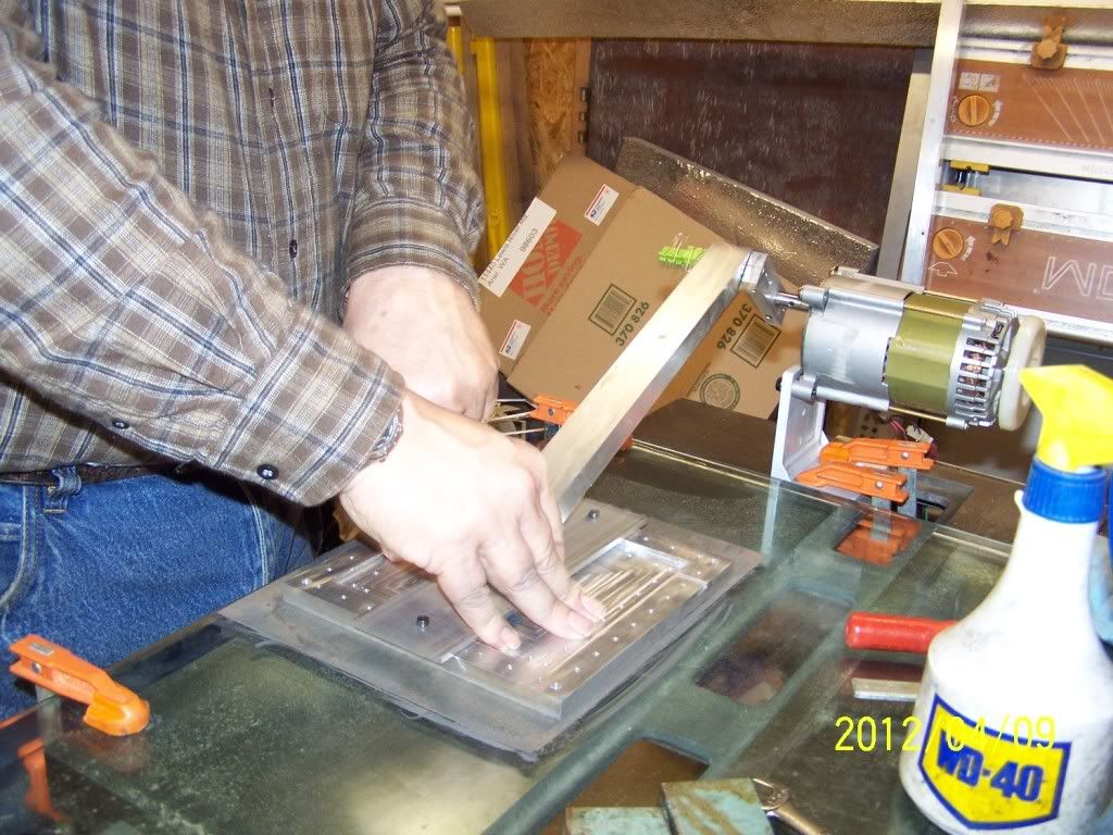
Well I have a warped bed just like Micheal. I think I can correct it though so I rigged this up.
[img]http://i132.photobucket.com/albums/q3/D ... 0_1238.jpg[/img]
[img]http://i132.photobucket.com/albums/q3/D ... 0_1240.jpg[/img]
[img]http://i132.photobucket.com/albums/q3/D ... 0_1241.jpg[/img]
[img]http://i132.photobucket.com/albums/q3/D ... 0_1238.jpg[/img]
[img]http://i132.photobucket.com/albums/q3/D ... 0_1240.jpg[/img]
[img]http://i132.photobucket.com/albums/q3/D ... 0_1241.jpg[/img]
Dave Sohlstrom
H-1 Tank
H-1 Tank

Re: I now own a mini CNC router and a 3D printer
Hey Dave, what are you doing there - sanding the H-1 table to flatten it?
If you saw my posts today, I ended up removing the stock table and using the narrow cross brace like you did. After printing today, it was a lot cooler unr the table than it was when I had the hoot bed mounted on the H-1 table. I think that open air helps keep it cooler. Now I need to make a decision on insulation.
Cheers,
Michael
Sublime Layers - my blog on Musings and Experiments in 3D Printing Technology and Art
Start Here:
A Strategy for Successful (and Great) Prints
Strategies for Resolving Print Artifacts
The Eclectic Angler
-
Dave_Sohlstrom
- Printmaster!
- Posts: 101
- Joined: Mon Mar 26, 2012 5:07 pm
- Location: Ariel, WA
Re: I now own a mini CNC router and a 3D printer
Yes I am lapping the table flat. It had a twist to it. I am still having trouble getting it dialed in on the machine. My next course of action would be to scrape it in to the surface plate but that takes a long time to do.
I saw your post on your new table good to hear it is working well. insulation will never hurt. Lack of it could still let the heat bow the table with heat one side cool the other.
I saw your post on your new table good to hear it is working well. insulation will never hurt. Lack of it could still let the heat bow the table with heat one side cool the other.
Dave Sohlstrom
H-1 Tank
H-1 Tank

Re: I now own a mini CNC router and a 3D printer
Nice looking routing on your Tank Dave.
~PartDaddy
SeeMeCNC Owner & Founder
Blackpoint Engineering is SeeMeCNC
Since 1996
SeeMeCNC Owner & Founder
Blackpoint Engineering is SeeMeCNC
Since 1996
-
Dave_Sohlstrom
- Printmaster!
- Posts: 101
- Joined: Mon Mar 26, 2012 5:07 pm
- Location: Ariel, WA
Re: I now own a mini CNC router and a 3D printer
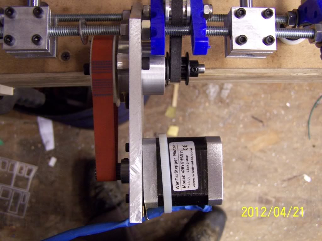
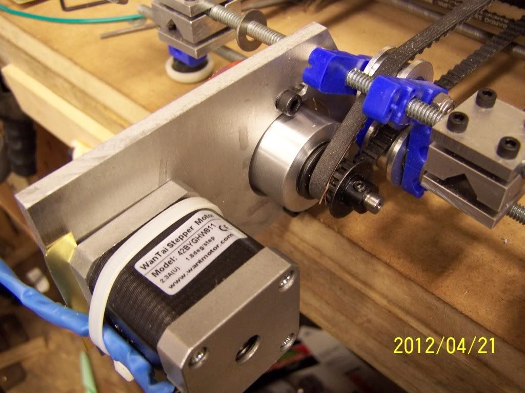
Well the Y axis just got Granny gear. While waiting for parts to arrive for the new hot end I decided that I would stretch the printer X axis and while I had the thing apart I discovered I had the parts to add a 4 to 1 reduction to the Y axis. Here are the results. If you stop the table from moving it just slides the whole machine across the table it is sitting on. Went from 1000 steps per inch to 4000 per inch. Still have to fine tune it. As you can see I had to do some shimming to get the new belt to track. Discovered the plate I used had a bow in it.
[img]http://i132.photobucket.com/albums/q3/D ... 0_0316.jpg[/img]
[img]http://i132.photobucket.com/albums/q3/D ... 0_0315.jpg[/img]
[img]http://i132.photobucket.com/albums/q3/D ... 0_0314.jpg[/img]
[img]http://i132.photobucket.com/albums/q3/D ... 0_0316.jpg[/img]
[img]http://i132.photobucket.com/albums/q3/D ... 0_0315.jpg[/img]
[img]http://i132.photobucket.com/albums/q3/D ... 0_0314.jpg[/img]
Dave Sohlstrom
H-1 Tank
H-1 Tank
-
michaellatif
- Printmaster!
- Posts: 357
- Joined: Mon Mar 26, 2012 1:34 pm
- Location: RTP, NC
Re: I now own a mini CNC router and a 3D printer
That looks cool Dave. I wish I had the tools to machine aluminum like you Dave!
Mike Latif
H-1 #3
H-1 #3
-
Dave_Sohlstrom
- Printmaster!
- Posts: 101
- Joined: Mon Mar 26, 2012 5:07 pm
- Location: Ariel, WA
Re: I now own a mini CNC router and a 3D printer
Mike
It has taken a lot of years and a lot of money to get the shop where it is today. Now I have to design and build a CNC router that will take a 18"X24" sheet of material.
It has taken a lot of years and a lot of money to get the shop where it is today. Now I have to design and build a CNC router that will take a 18"X24" sheet of material.
Dave Sohlstrom
H-1 Tank
H-1 Tank
-
Eaglezsoar

- ULTIMATE 3D JEDI
- Posts: 7185
- Joined: Sun Apr 01, 2012 5:26 pm
Re: I now own a mini CNC router and a 3D printer
Dave, when you milled out the holes to fit the linear bearings, did you use an appropriate size drill bit or something else?Dave_Sohlstrom wrote:Here are the 4 linear bearing blocks for the Z axis on the H-1 Tank. Will be cutting them apart and adding some taped holes on the edges just in case. One thing I have discovered is because of the increase in weight of the X axis and extruder I an loosing steps if I rapid up at to high a feed rate. limited to about 16 IPM.
I think that I will be designing a counter weight system so the lear screws do not have to lift all of the weight.
[img]http://i132.photobucket.com/albums/q3/D ... 0_1232.jpg[/img]
My linear bearings are 8mm ID and 15mm OD and I thought I could get away with using a 15mm drill bit for the holes for
the linear bearings. Do you have any opinions that could save me time down the road?
“ Do Not Regret Growing Older. It is a Privilege Denied to Many. ”
-
Dave_Sohlstrom
- Printmaster!
- Posts: 101
- Joined: Mon Mar 26, 2012 5:07 pm
- Location: Ariel, WA
Re: I now own a mini CNC router and a 3D printer
Carl
These bearing blocks were machined on my vert mill. The holes for the bearings in my case are 16mm so I drilled 13mm the biggest metric drill I own and then bored them out to 16mm using my boring head. The mill has 3 axis DRO so I could get all the bearing hole located in all 4 blocks correctly. If you get a hole off by a few thou it can through the throw the whole thing off when assembled.
These bearing blocks were machined on my vert mill. The holes for the bearings in my case are 16mm so I drilled 13mm the biggest metric drill I own and then bored them out to 16mm using my boring head. The mill has 3 axis DRO so I could get all the bearing hole located in all 4 blocks correctly. If you get a hole off by a few thou it can through the throw the whole thing off when assembled.
Dave Sohlstrom
H-1 Tank
H-1 Tank
Re: I now own a mini CNC router and a 3D printer
Great looking parts Dave! Wow.
~PartDaddy
SeeMeCNC Owner & Founder
Blackpoint Engineering is SeeMeCNC
Since 1996
SeeMeCNC Owner & Founder
Blackpoint Engineering is SeeMeCNC
Since 1996
-
Dave_Sohlstrom
- Printmaster!
- Posts: 101
- Joined: Mon Mar 26, 2012 5:07 pm
- Location: Ariel, WA
-
Dave_Sohlstrom
- Printmaster!
- Posts: 101
- Joined: Mon Mar 26, 2012 5:07 pm
- Location: Ariel, WA
Re: I now own a mini CNC router and a 3D printer
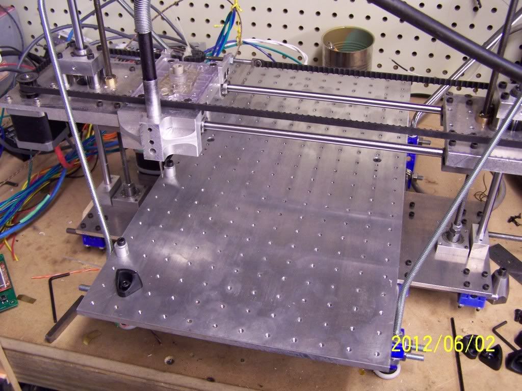
Here is what 276 4mm taped holes and 8 mounting holes gets you. A table that is 9.5"X18" so I can route large parts. I have to reset the part if it is bigger than 8X8. I've been routing model tow boat parts for some guys in CA.
[img]http://i132.photobucket.com/albums/q3/D ... 0_0370.jpg[/img]
[img]http://i132.photobucket.com/albums/q3/D ... 0_0370.jpg[/img]
Dave Sohlstrom
H-1 Tank
H-1 Tank
-
michaellatif
- Printmaster!
- Posts: 357
- Joined: Mon Mar 26, 2012 1:34 pm
- Location: RTP, NC
Re: I now own a mini CNC router and a 3D printer
That is too cool! Does the table move or is it fixed?
Mike Latif
H-1 #3
H-1 #3
Re: I now own a mini CNC router and a 3D printer
Hey thats not a printer!
Looking good Dave, nice tooling plate. I need to make one for my mill.
I have some 1" mic-6 set aside and a dxf for the waterjet (cheating?)
I also have a very nice tapping arm to use as well. The hardest part of the deal is shelling out the cash for all those heli-coils...ouch
Looking good Dave, nice tooling plate. I need to make one for my mill.
I have some 1" mic-6 set aside and a dxf for the waterjet (cheating?)
I also have a very nice tapping arm to use as well. The hardest part of the deal is shelling out the cash for all those heli-coils...ouch
JTCUSTOMS
“Things may come to those who wait...but only the things left by those who hustle.” Abraham Lincoln
“Things may come to those who wait...but only the things left by those who hustle.” Abraham Lincoln
-
Dave_Sohlstrom
- Printmaster!
- Posts: 101
- Joined: Mon Mar 26, 2012 5:07 pm
- Location: Ariel, WA
Re: I now own a mini CNC router and a 3D printer
Mike
Yes it is bolted to the table so moves in Y axis. With the 4to1 reduction on the Y axis I can move it at 50"per min and rapid even faster without missing steps.
JT
Heli-coils would be nice but I think I can get away with out them. With a water jet available you can make all kinds of neat mods to the machine.
Dave Sohlstrom
H-1 Tank
H-1 Tank
Re: I now own a mini CNC router and a 3D printer
Dave_Sohlstrom wrote:When I get the heated bed up and running I will be printing molds for wax patterns used for lost wax investment casting.
Hi Dave, have you thought about doing lost foam casting instead?
The mods you made are spectacular.
-
Dave_Sohlstrom
- Printmaster!
- Posts: 101
- Joined: Mon Mar 26, 2012 5:07 pm
- Location: Ariel, WA
Re: I now own a mini CNC router and a 3D printer
flink
The trouble with lost foam is three fold. 1 Hard to get good surface texture. 2 Foam does not machine well. so it is hard to make patterns in the small sizes I'm working in. 3 For lost foam to work well you have to have the right density of foam so it burns out at a controlled rate and gives good casting.
The people making engine castings for cars are using lost foam. They have very expensive molds that they use to cast the foam into and have to make multi part patterns and glue them together.
Dave
Dave Sohlstrom
H-1 Tank
H-1 Tank