Yet another Duet-to-HE280 accelerometer probe adapter
Re: Yet another Duet-to-HE280 accelerometer probe adapter
I've abandoned my version, I can't speak for trash80, he has his own thread so post there and ask.
Sublime Layers - my blog on Musings and Experiments in 3D Printing Technology and Art
Start Here:
A Strategy for Successful (and Great) Prints
Strategies for Resolving Print Artifacts
The Eclectic Angler
Re: Yet another Duet-to-HE280 accelerometer probe adapter
Thanks. I was looking at his and it seems to still be active.
-
leadinglights

- Plasticator
- Posts: 18
- Joined: Tue May 24, 2016 6:39 am
Re: Yet another Duet-to-HE280 accelerometer probe adapter
I have looked at and tried very many methods although I dismissed FSRs because of an antipathy going back to a project some years ago. so far the best I have found are piezo disk based sensors followed by optical such as David Crocker's IR sensor and the better class of deployable switches such as the bltouch.mhackney wrote:Have you looked at FSRs? They are an excellent solution that work under a wide variety of conditions, reliably. There is no reason why an effector/carriage couldn't be designed with an FSR rather than a piezoelectric sensor.
But, on to your question, yes F1800 and that is at the low end. The stock SeeMeCNC configuration for probe speed is much higher. My assertion (and verified through many experiments) was that high impact speed with an accelerometer probe can cause "distortion" in the mechanism. And, I have videos to prove that is indeed the case. The effector actually tilts slightly when it hits the bed surface. The slower you can probe, the less pronounced this is. But with accelerometers, you are measuring the rate of change of speed. If the speed is very low, the system just "pushes" and the probe does not trigger. If you start with a high speed, the contact can be detected.
We worked on making the accelerometer more sensitive by using its 2g full range rather than the 16g the SeeMeCNC code configures. We also changed the firmware acceleration settings (Duet) dynamically at probe time to remove the actual probing movement accelerations, and David Crocker implemented a special firmware feature to allow us to arm the probe when it was positioned and ready probe. THere were quite a few other optimizations I configured and tested too. At the end of the day, bed surface, effector mass, and lots of variables that I wasn't able to characterize affect the accelerometer triggering sensitivity.
I am quite surprised that people are using semiconductor accelerometers as they essentially are measuring a small change in acceleration against a background of gravity. Although this is obviously possible, it does need a great deal of signal processing. A piezoelectric accelerometer only measures changes in acceleration and should be easier to use.
I have made a piezo disk based accelerometer and found it quite sensitive if held in the hand and tapped lightly on a glass plate. This success was not repeated when held in a light milling machine and cycled up and down against a surface - I assume that the deceleration of the milling head was very small.
Re: Yet another Duet-to-HE280 accelerometer probe adapter
Hey Mike, I don't know if you looked at FSRs with the JohnSL interface board. If not, you should. I have been running delta printers using this setup with absolutely perfect results for a couple of years, printing nearly everyday. Other than the initial install, which really was not a problem, I really can't imagine a more reliable, robust and precise probing system. It works very well.
The challenge with IR probes like David's (and I have one) is that it is sensitive to the IR properties of the bed. For PEI, one must paint the back of the PEI black but even then, since I do spot repairs on my PEI with CA adhesive (which has different IR characteristics) I get inconsistent results. Other surfaces have different characteristics which affect probing and probe trigger height. Similarly the accelerometer probe is also sensitive to different print surfaces (primarily the hardness characteristic) and even mass of the effector. The FSRs with JohnSL have none of these problems. I also have looked at and done extensive testing on many probing systems for my3D printers and CNC milling machines. I have one RostockMax V1 setup with FSRs/JohnSL, David's IR probe and the SeeMeCNC accelerometer probe simultaneously. I can quickly change probing in config.g (and if using FSRs, lock the bed rigidly) and do head to head comparisons. Here's a real example of why this is important to me:
I have 15 borosilicate plates with different surface materials, PEI, FabLam,PrintinZ, Garolite, bare glass, BuildTak, for printing different filaments and/or getting different aesthetics on the first layer. With the FSRs I can literally remove a bed, replace it with any one from the list, run autocalibration (Duet with dc42 RepRapFirmware) and print with perfect results. No probe tuning, probe trigger height tuning or any other change required. There is no way I could do that with either the IR probe or accelerometer probe.
How would the piezo probe work with PEI adhered to the glass?
cheers,
Michael
Sublime Layers - my blog on Musings and Experiments in 3D Printing Technology and Art
Start Here:
A Strategy for Successful (and Great) Prints
Strategies for Resolving Print Artifacts
The Eclectic Angler
-
leadinglights
- Plasticator
- Posts: 18
- Joined: Tue May 24, 2016 6:39 am
Re: Yet another Duet-to-HE280 accelerometer probe adapter
My experience with piezo disks sounds the same as yours with FSRs, rock solid and reliable. It is hard to make any more claims than that as there is only a tiny declared user base, 4 to 6 people but all of those say only good things about them. In the real world there must be some people who have tried piezo disks them and become frustrated and gone onto something else - I know this is true of FSRs but they have a much larger user base. It would be great if we could hear of the problems so that they could be addressed.
The biggest problems with piezo disk sensors are not technical but human and organizational: There is only one supplier of amplifiers (Moriquendi) who makes them more from helpfulness and is showing signs of maker fatigue. Piezo disks can vary in sensitivity, polarity and physical geometry of the connections. Drilling holes in piezo disks is fraught with risks both to the disk and to the drillers fingers.
On the plus side, the only practical limit to the sensitivity of piezo disks of is mechanical noise in the system while resolution and repeatibility are at the limits of what the firmware can show: Using Arduino Mega/Ramps/Repetier firmware and many probing repeats of a 5 by 5 matrix there are no differences between runs of more than 1 LS digit while contact force is about 10 grams and duration of the contact from the nozzle touching to being lifted is a little over 10ms. Virtual immunity to the physical characteristics of the build surface has proven useful in my experiments with the vacuum hold-down
Increasingly there appear to be no significant technical downsides but I genuinely would like to hear back from anybody who has tried piezo disks and failed.
Mike
Re: Yet another Duet-to-HE280 accelerometer probe adapter
@leadinglights, what about their ability to handle multiple surfaces and not just plain borosilicate without any changes to probe sensitivity, etc? My experience spans the gamut of bed surfaces AND multiple printers (i.e. different effectors, motion control mechanics, .9 vs 1.8 steppers, bed sizes and masse, etc) so I am able to state definitively that that FSR probing (with the JohnSL) works reliably, repeatably and with no configuration changes under essentially all conditions. I'm trying to establish the degree of testing and capability of the piezo sensors, what is the current range of testing that has been done on different bed surfaces, different printers (primarily bed size and mass, effector mass and .9 vs 1.8 degree steppers)? I really curious!
I assert that the issues that are reported with FSRs are now urban legend and predate the JohnSL board back in the "dark firmware" days. I've had several hundred (>250) people contact me that they have followed my tutorials and love FSRs. 2 of those had issues and in both cases the issue was due to improper mounting - the FSR contact plunger was binding. My new "FSR Plate" design completely eliminates this possibility. I don't get anything out of promoting FSRs other than my personal enjoyment that they work and that others are successful with them.
thanks,
Michael
Sublime Layers - my blog on Musings and Experiments in 3D Printing Technology and Art
Start Here:
A Strategy for Successful (and Great) Prints
Strategies for Resolving Print Artifacts
The Eclectic Angler
-
Xenocrates
- ULTIMATE 3D JEDI
- Posts: 1561
- Joined: Wed Sep 23, 2015 2:55 pm
Re: Yet another Duet-to-HE280 accelerometer probe adapter
If I may interject, I believe that the primary advantage from my perspective on FSR's is that they have some amount of current in the system, and hopefully provide more noise immunity, without the spiking voltages (I believe up to 35V was mentioned by you at some point, Leadinglights, but I may be wrong and the peak voltages may have changed with the design tweaks and force optimizations). However, they are less well suited to use on the effector, as I am not aware of a design which has a central hole for filament to pass through.
Personally, I would rather have the sensor on the bed, as I work with multiple effector assemblies, and some would be very annoying to get FSR's working on. I would not be particularly surprised if a Kraken or Chimera mounting design took some major effort to be able to calibrate multiple nozzles well, although you may well have done it already (If so, congratulations, it is quite a great thing there). Another issue I might have with peizo's is that depending on the noise that gets to the disk, they may shake somewhat while printing. While for most environments this shouldn't be a major concern, I am aware of a number of labs where seeing a 1V AC coupled signal on a shielded, twisted, and grounded 2 ft cable was on the low end, while the usually unshielded wiring of a printer of at least 700mm (Bowden length on a V2 or V3), may see major noise in such a place (Admittedly, it was an industrial electronics lab, with 3 phase power, and a large number of electromechanical relays, although none of that was particularly active at the time, and the room itself is shielded from the outside). There is also the disadvantage of adding mass to the effector assembly.
Both are technically quite sound, and feats of cleverness from people who are very much not being paid enough. I believe it will come down to taste, and support for the two options, especially commercially. Until the PE elements, with a drilled center hole are more available from vendors such as Ultibots, Matterhackers, or Tridprinting, or another site that is 3D printing focused, while being neither ebay nor alibaba, I don't think a lot of people will choose them.
Machines:
Rostock Max V2, Duet .8.5, PT100 enabled E3D V6 and volcano, Raymond style enclosure
Automation Technology 60W laser cutter/engraver
1m X-carve router
Sic Transit Gloria Mundi
01-10011-11111100001
Rostock Max V2, Duet .8.5, PT100 enabled E3D V6 and volcano, Raymond style enclosure
Automation Technology 60W laser cutter/engraver
1m X-carve router
Sic Transit Gloria Mundi
01-10011-11111100001
-
leadinglights
- Plasticator
- Posts: 18
- Joined: Tue May 24, 2016 6:39 am
Re: Yet another Duet-to-HE280 accelerometer probe adapter
Having worked for many years in product design I know that many initial designs are well received but turn out to have fatal flaws that even some bright cookies were unable to see. Somewhere between one in three and one in ten designs reach production - and the market even then may not be interested. I say the foregoing because those years have left me with a critical judgement and a willingness to kick even well loved projects off the pedestal on which I have put them - but that has not yet happened to the piezo disk sensors.
Down to cases and questions: Michael, you ask about piezo sensors ability to handle multiple surfaces without introducing a fudge factor to account for surface softness etc., I have not done a purposeful check on this but prints on surfaces as diverse as "Carp" brand Tufnol (approx Garolite), acrylic, glass with Kapton, glass with Wolfbite, 3M Blue Tape have worked without babystepping from my 0.0mm offset. Thin films including overhead projector film and the film from lamination pouches used with the vacuum stage seem to be O.K., but need more work before I can swear to their invariability. As far as printers go, my Delta printer was fitted with 0.9° at the same time that I introduced the piezo sensors so I can't say about 1.8° steppers on the Delta. I do have a Cartesian printer on which I have had to set the touch sensitivity to somewhere around 100 grams, 10 times worse than on the Delta, because it shakes at the end of each X and Y movement and this mechanical noise trips the sensors. Even this could be resolved by having a brief delay after each X or Y movement immediately before probing but this option is not available in the firmware that I am using.
Xenocrates, the high voltage that you mention is what you can get from a piezo disk and it does mean that some protective diodes should be a part of the amplifier - without these it is not impossible that dropping a screwdriver on the build stage could cause the MCU on your controller to fall over. As far as noise goes, the piezo disk itself is basically a capacitor and has quite a large value - 20nF on the 27mm units. This acts as a suppressor and minimizes electrostatic noise. Magnetically induced noise I minimize by having the amplifier fairly close to the disks so that the long run to the controller is from a low impedance output. The noise that I do get is from mechanical effects and should not be of any concern as the controller should only be monitoring the sensor output during a Z probe call.
I have not come across a FSR used in the effector of a Delta printer but DjDemonD has a Piezo based one working very reliably.
As I said in the opening paragraph, I don't know which is best; but I suspect that if the Piezo disk had been used first FSRs would have a major uphill battle to get any traction.
Mike
Re: Yet another Duet-to-HE280 accelerometer probe adapter
Mike, this is the sort of information I was looking for, thanks! As you know, so many people post comments like "it works" and they are correct - it works for their use case but maybe not others. The range of bed surfaces you list tells me the sensor is not sensitive to the "dampening' effect that accelerometers experience.
You mention sensitivity to mechanical noise, that's why I asked about .9 vs 1.8 degree steppers. I can literally tell you which stepper and how many microsteps based on how the accelerometer responds. But there is no difference in response with FSRs. What sort of mechanical noise issues are you talking about? Primarily vibration? This might be where the new "arming" implementation and the ability to change microsteps dynamically in dc42 could help.
You mention sensitivity to mechanical noise, that's why I asked about .9 vs 1.8 degree steppers. I can literally tell you which stepper and how many microsteps based on how the accelerometer responds. But there is no difference in response with FSRs. What sort of mechanical noise issues are you talking about? Primarily vibration? This might be where the new "arming" implementation and the ability to change microsteps dynamically in dc42 could help.
Sublime Layers - my blog on Musings and Experiments in 3D Printing Technology and Art
Start Here:
A Strategy for Successful (and Great) Prints
Strategies for Resolving Print Artifacts
The Eclectic Angler
-
leadinglights
- Plasticator
- Posts: 18
- Joined: Tue May 24, 2016 6:39 am
Re: Yet another Duet-to-HE280 accelerometer probe adapter
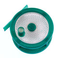
As far as mechanical sensitivity goes, I think that I can show you just how bad or good it gets. Picture below is of a probe pushing on a 20mm piezo disk as speeds from 0.5mm/sec to 3mm/sec. The ripples are from the stepper motor and reach resonance on the second trace (1mm/sec) where each wiggle is 0.0025mm of movement.
It looks quite bad until you know that this is from a milling machine with ball screws and 1.8° half step steppers which I was using as a test jig - no nice plastic to absorb the vibration and it is still usable.
Mike
Mike
-
thingismith

- Printmaster!
- Posts: 68
- Joined: Sat Apr 08, 2017 7:45 pm
Re: Yet another Duet-to-HE280 accelerometer probe adapter
I'm only getting an "Z probe was not triggered during move" every hit on the bed when it goes through the calibration and no lights are blinking off or on on my hotend or trinket, just the always-on green light on the trinket and the blue light on the hotend.
I entered my results pre-duet into my config (my probe was working on the Rambo), so my test print came out good (a little off on the size ratios), so I know the hotend is working. Any ideas for troubleshooting? Did I miss a step in programming? I've updated the bed.g and already tried upping the M558 and M665 H parameters a bit, no dice.
I know I'm going to eventually break down and go FSR, but I'd like to see if I can get this working first.
Re: Yet another Duet-to-HE280 accelerometer probe adapter
This is one of the main reasons I stopped supporting this. It is too dependent on surface hardness for my requirements and several other factors affect sensitivity that don't cause a problem with FSRs.
Sublime Layers - my blog on Musings and Experiments in 3D Printing Technology and Art
Start Here:
A Strategy for Successful (and Great) Prints
Strategies for Resolving Print Artifacts
The Eclectic Angler
Re: Yet another Duet-to-HE280 accelerometer probe adapter
Does the nozzle crash into the bed, or not touch the bed at all when probing?thingismith wrote:I'm only getting an "Z probe was not triggered during move" every hit on the bed when it goes through the calibration and no lights are blinking off or on on my hotend or trinket, just the always-on green light on the trinket and the blue light on the hotend.
I entered my results pre-duet into my config (my probe was working on the Rambo), so my test print came out good (a little off on the size ratios), so I know the hotend is working. Any ideas for troubleshooting? Did I miss a step in programming? I've updated the bed.g and already tried upping the M558 and M665 H parameters a bit, no dice.
I know I'm going to eventually break down and go FSR, but I'd like to see if I can get this working first.
-
thingismith
- Printmaster!
- Posts: 68
- Joined: Sat Apr 08, 2017 7:45 pm
Re: Yet another Duet-to-HE280 accelerometer probe adapter
It taps it... I have the correct height from before, so I gave it an extra mm to touch it. I had added up to an extra 10mm, crashing into the bed.dc42 wrote: Does the nozzle crash into the bed, or not touch the bed at all when probing?
I just noticed the sensitivity setting in the trinket's .ino, so when I get a chance I'm going to try increasing it from 20. I'll also try quoting out the reset command, maybe that's causing my error?
Any other suggestions?
Re: Yet another Duet-to-HE280 accelerometer probe adapter
Either the adapter isn't registering a hit, or it is but it isn't being communicated to the firmware running on the Duet.
Have you verified that you are using the correct wiring from the adapter back to the Duet, and the correct M558 command in the config.g file?
Does the adapter have a LED that flashes when it registers a hit?
Have you verified that you are using the correct wiring from the adapter back to the Duet, and the correct M558 command in the config.g file?
Does the adapter have a LED that flashes when it registers a hit?
Re: Yet another Duet-to-HE280 accelerometer probe adapter
Honestly, it is not worth the time and aggravation trying to get this to work. It is almost certain that the issue is the adapter is not seeing the trigger event due to the wide variability in probing conditions. This is why I abandoned this approach.
Sublime Layers - my blog on Musings and Experiments in 3D Printing Technology and Art
Start Here:
A Strategy for Successful (and Great) Prints
Strategies for Resolving Print Artifacts
The Eclectic Angler
-
thingismith
- Printmaster!
- Posts: 68
- Joined: Sat Apr 08, 2017 7:45 pm
Re: Yet another Duet-to-HE280 accelerometer probe adapter
Okay, I just switched everything over to the FSR (from Ultibot) and the Duet's still not reading my hits. The JohnSL is indicating that the taps are registering, but my Duet's just not getting them. What's going on??!! Maybe I have the config or bed wrong?
Config:
Bed:
Config:
Code: Select all
; Configuration file for SeeMeCNC Rostock MAX V2

; Communication and general
M111 S0                             	; Debug off
M550 PRandy MaxV2			; Machine name and Netbios name (can be anything you like)
M551 Preprap                        	; Machine password (used for FTP)
;*** If you have more than one Duet on your network, they must all have different MAC addresses, so change the last digits
M540 P0xBE:0xEF:0xDE:0xAD:0xFE:0xEA 	; MAC Address
;*** Wifi Networking
M552 S1 				; Enable WiFi

M555 P2                           	; Set output to look like Marlin
M575 P1 B57600 S1			; Comms parameters for PanelDue

G21                                 	; Work in millimeters
G90                                	; Send absolute coordinates...
M83                                 	; ...but relative extruder moves

; Axis and motor configuration
M569 P0 S1				; Drive 0 goes forwards
M569 P1 S0				; Drive 1 goes forwards
M569 P2 S1				; Drive 2 goes forwards
M569 P3 S0				; Drive 3 goes forwards
M569 P4 S1				; Drive 4 goes forwards
M574 X2 Y2 Z2 S1			; set endstop configuration (all endstops at high end, active high)
;*** The homed height is deliberately set too high in the following - you will adjust it during calibration
M665 R142.540 L290.8 B145 H378.2 X0 Y0 Z0   ; set delta radius, diagonal rod length, printable radius and homed height
M666 X0 Y0 Z0    ; put your endstop adjustments here, or let auto calibration find them
M350 X16 Y16 Z16 E16 I1    			; Set 16x microstepping with interpolation
M92 X80 Y80 Z80				; Set axis steps/mm
M906 X1000 Y1000 Z1000 E800 I60		; Set motor currents (mA) and increase idle current to 60%
M201 X1000 Y1000 Z1000 E1000		; Accelerations (mm/s^2)
M203 X20000 Y20000 Z20000 E3600		; Maximum speeds (mm/min)
M566 X1200 Y1200 Z1200 E1200		; Maximum instant speed changes mm/minute

; Thermistors
M305 P0 T100000 B3950 R4700 H30 L0	; Put your own H and/or L values here to set the bed thermistor ADC correction
M305 P1 T100000 B4388 R4700 H30 L0	; Put your own H and/or L values here to set the first nozzle thermistor ADC correction
;M305 P2 T100000 B4388 R4700 H30 L0	; Put your own H and/or L values here to set the second nozzle thermistor ADC correction
M570 S180				; Hot end may be a little slow to heat up so allow it 180 seconds

; Fans
M106 P1 H-1 				; disable thermostatic mode for fan 1

; Tool definitions
M563 P0 D0 H1                       	; Define tool 0
G10 P0 S0 R0                        	; Set tool 0 operating and standby temperatures
;*** If you have a single-nozzle build, comment the next 2 lines
M563 P1 D1 H2                      	; Define tool 1
G10 P1 S0 R0                       	; Set tool 1 operating and standby temperatures
M92 E1025:1025                      	; Set extruder steps per mm

; Z probe and compensation definition
;*** If you have an IR zprobe instead of a switch, change P4 to P1 in the following M558 command
M558 P4 X0 Y0 Z0         ; Z probe is a switch and is not used for homing any axes
G31 X0 Y0 Z P500     ; Set the zprobe height and threshold (put your own values here, Set the zprobe offset and threshold (determine your printer's Z offset value). For a delta, use zero X and Y offset.

;*** If you are using axis compensation, put the figures in the following command
M556 S78 X0 Y0 Z0                   	; Axis compensation here

T0 ; select first hot endCode: Select all
; Auto calibration routine for SeeMeCNC Rostock MAX V2
;
; About the G30 S parameter
; Used to specify what calibration computation to perform.
;
; S=-1 Don't adjust anything, just print the height error at each probe point
; S=0 Equivalent to S=<number_of_points_probed>
; S=3 Adjust homing switch corrections only
; S=4 Adjust homing switch corrections and delta radius
; S=6 Adjust homing switch corrections, delta radius, and X and Y tower position offsets
; S=7 Adjust homing switch corrections, delta radius, X and Y tower position offsets, and diagonal rod length

M561                  ; clear any bed transform, otherwise homing may be at the wrong height
G31 X0 Y0               ; don't want any probe offset for this
M558 P3                  ; drive mod pin on Probe Z connector LOW
G28                  ; home the printer

;*** Remove the following line if your Z probe does not need to be deployed
;M98 Pdeployprobe.g    ; deploy the mechanical Z probe

; The first time the mechanical probe is used after deployment, it gives slightly different results.
; So do an extra dummy probe here. The value stored gets overwritten later. You can remove this if you use an IR probe.

G30 P0 X0 Y0 Z-99999

; Probe the bed and do 6- or 7-factor auto calibration
G30 P0 X-69.28 Y-40.00 Z-99999 H0.0   ; X tower
G30 P1 X0.00 Y-80.00 Z-99999 H0.0   ; between X-Y towers
G30 P2 X69.28 Y-40.00 Z-99999 H0.0   ; Y tower

G30 P3 X69.28 Y40.00 Z-99999 H0.0   ; between Y-Z towers

G30 P4 X0.00 Y80.00 Z-99999 H0.0   ; Z tower

G30 P5 X-69.28 Y40.00 Z-99999 H0.0 ; between Z-X towers

G30 P6 X-34.64 Y-20.00 Z-99999 H0.0   ; X tower

G30 P7 X0.00 Y-40.00 Z-99999 H0.0   ; between X-Y towers

G30 P8 X34.64 Y-20.00 Z-99999 H0.0   ; Y tower

G30 P9 X34.64 Y20.00 Z-99999 H0.0   ; between Y-Z towers

G30 P10 X0.00 Y40.00 Z-99999 H0.0   ; Z tower

G30 P11 X-34.64 Y20.00 Z-99999 H0.0   ; between Z-X towers

G30 P12 X0 Y0 Z-99999 H0.0 S6   ; center and auto-calibrate 6 factors


;*** Remove the following line if your Z probe does not need to be retracted
;M98 Pretractprobe.g   ; retract the mechanical Z probe

G1 X0 Y0 Z150 F10000   ; get the head out of the way of the bed
Re: Yet another Duet-to-HE280 accelerometer probe adapter
See https://duet3d.com/wiki/Connecting_a_Z_ ... tor.28s.29. If you have connected the JohnSL board to the Z probe connector, you should use P5 in the M558 command instead of P4.
-
thingismith
- Printmaster!
- Posts: 68
- Joined: Sat Apr 08, 2017 7:45 pm
Re: Yet another Duet-to-HE280 accelerometer probe adapter
I have it connected to the Endstop Connector, as Michael instructed. In his post, he has his wires on the endstop Gray, Red, Black...according to the above, shouldn't it be Red, Gray, Black? Doesn't really matter, that change didn't make a difference for me.Connect its Vcc, Output and Ground pins to 3V3, STP and GND respectively on the E0 endstop connector, and select mode 4.
-
thingismith
- Printmaster!
- Posts: 68
- Joined: Sat Apr 08, 2017 7:45 pm
Re: Yet another Duet-to-HE280 accelerometer probe adapter
I decided to try connecting it to the Z Probe Connector, and it worked! Still can't figure out why it didn't work on the E0 Endstop or why my trinket/accelerometer wouldn't work, but I'm just glad I'm finally getting results.