While i wait for my kit to arrive.
I've been researching and gathering information for my build.
What have you guys been doing for the heated build plates?
From what I gather on the forums that I've seen. People use an aluminum heat spreader on top of the heater then add boro glass on top.
Is this the way to do it to get even heat distribution?
It seems like the case from my researching. I found on another forum that heating the boro too fast will also cause the boro to flex. Adding the aluminum plate in between the heater and the boro helps to minimize this along with pid heatbed tuning of some sort.
https://groups.google.com/forum/?fromgr ... Ckwe_8vez4 and https://groups.google.com/forum/#!topic ... discussion
How many of you guys are using onyx with aluminum heat spreader and boro glass?
Just wanted to get some opinions. I have a cnc router so can cut out custom aluminum heat spreaders fairly quickly. What thickness should be used? would 1/8" thick aluminum be enough?
or do I even need an aluminum heat spreader with the onyx design? Could I just set the boro right on top of it?
Maybe the boro from seemecnc is thick enough that it wont flex?
Do I even need the boro If I'm using the aluminum heat spreader?
Another rostock max build
Another rostock max build
Last edited by cambo3d on Thu Feb 28, 2013 6:27 pm, edited 2 times in total.
My rostock build log http://forum.seemecnc.com/viewtopic.php?f=42&t=1228

Re: Another rostock max build
cambo3D, the Onyx actually warps when it gets hot and that can stress glass clamped on top. It also does not distribute the heat evenly. I am now manufacturing a 1/8" aluminum heat dissipation plate for the Rostock MAX that will 1) give you VERY even temperature across the entire surface and 2) provide a very flat warp free surface. With it installed you have many options for print surface:
1) blue tape - great for PLA but I occasionally print ABS directly on it at 80°C
2) Kapton - very good for ABS. I will also be offering 12" x 12" pieces of Kapton next week when I list the heat dissipators
3) directly to the aluminum - I've been printing on aluminum with hairspray for about a year with great results.
4) with the borosilicate glass on top of the aluminum with blue tape, Kapton or hair spray
All of these are reliable methods. Since I had already ordered the borosilicate glass before I designed and started manufacturing the aluminum heat dissipator, I use it with hair spray.
Regards,
Michael
Sublime Layers - my blog on Musings and Experiments in 3D Printing Technology and Art
Start Here:
A Strategy for Successful (and Great) Prints
Strategies for Resolving Print Artifacts
The Eclectic Angler
-
Polygonhell
- ULTIMATE 3D JEDI
- Posts: 2417
- Joined: Mon Mar 26, 2012 1:44 pm
- Location: Redmond WA
Re: Another rostock max build
FWIW all PCB based heaters warp when they get hot, which is why you need at least a glass sheet on top.
It's possible because of it's size that it puts additional stress on the glass. On most RepRaps the bed is actually mounted the other way up so it warps away from the glass, but it does impact the speed of heating somewhat.
I see perhaps a 10 degrees variation across the bed, which is actually not horrible.
I'm still using one of the circular glass sheets SeeMeCNC are selling with no cracking issues, though it is thicker than I would prefer, which means more thermal mass and longer to heat up.
Printer blog http://3dprinterhell.blogspot.com/
Re: Another rostock max build
Thanks aluminum plate it is with the optional boro glass I have coming is the plan then.
I must have read the assembly instructions that geneb wrote 3x already just to make sure I have everything I need In anticipation of my kit arrival.
I ordered another power supply for the heat bed. Ordered connectors for the rrd lcd. Saved all the links to firmware, host, slicer software. Hopefully I'm not missing anything here.
Anyone know of a good cheep temperature meter that has a thermocouple?
My rostock build log http://forum.seemecnc.com/viewtopic.php?f=42&t=1228
-
Eaglezsoar

- ULTIMATE 3D JEDI
- Posts: 7159
- Joined: Sun Apr 01, 2012 5:26 pm
Re: Another rostock max build
http://www.amazon.com/gp/product/B0012V ... UTF8&psc=1 It sells for 19.95 and comes with a K thermocouple and seems accurate.cambo3d wrote:Thanks aluminum plate it is with the optional boro glass I have coming is the plan then.
I must have read the assembly instructions that geneb wrote 3x already just to make sure I have everything I need In anticipation of my kit arrival.
I ordered another power supply for the heat bed. Ordered connectors for the rrd lcd. Saved all the links to firmware, host, slicer software. Hopefully I'm not missing anything here.
Anyone know of a good cheep temperature meter that has a thermocouple?

Re: Another rostock max build
I've got the MN36 of the same brand listed above. I found the thermocouple to be very accurate. You can always double check it by putting the thermocouple in a glass of ice water. Should read 0*C or 32*F.
Word of advice though. Add some heat shrink or tape around banana plugs to wires area. My thermocouple no longer works because the wire inside broke.
Word of advice though. Add some heat shrink or tape around banana plugs to wires area. My thermocouple no longer works because the wire inside broke.
Re: Another rostock max build
So I was bored last night. I figured I would go ahead and make the lcd wiring harness, since I had already ordered the parts. (This was before I knew seemecnc guys were now including lcd adaptors.)
but anyway, I did it using the instructions without even having the machine yet. It wasn't difficult at all. I skipped the lengthy read on how to wire it with the included harness and just made my own. Took me about an hour. Here's how it looks. Probably will use the new adapters but I'll keep this as back up.
but anyway, I did it using the instructions without even having the machine yet. It wasn't difficult at all. I skipped the lengthy read on how to wire it with the included harness and just made my own. Took me about an hour. Here's how it looks. Probably will use the new adapters but I'll keep this as back up.
- Attachments
-
-
-
My rostock build log http://forum.seemecnc.com/viewtopic.php?f=42&t=1228
Re: Another rostock max build
just recieved my new kit, here's a first look at the new rambo lcd adapter board.
- Attachments
-
-
Last edited by cambo3d on Tue Mar 12, 2013 3:20 pm, edited 1 time in total.
My rostock build log http://forum.seemecnc.com/viewtopic.php?f=42&t=1228
Re: Another rostock max build
and here are some initial unpacking photos arrived safe. More to come stay tuned...
- Attachments
-
-
My rostock build log http://forum.seemecnc.com/viewtopic.php?f=42&t=1228
Re: Another rostock max build
Now you get to have the great fun of stripping tape and backing off all those laser cut parts!
Sublime Layers - my blog on Musings and Experiments in 3D Printing Technology and Art
Start Here:
A Strategy for Successful (and Great) Prints
Strategies for Resolving Print Artifacts
The Eclectic Angler
Re: Another rostock max build
moving right along, after taking the protective film off the big sheets. 99% of the laser cut parts came right out, there were some spots that needed a little extra force. no big deal. The quality looks good. No parts look skewed from my naked eye.
looks intimidating ehh....
There was only one spot in the laser cutting that was slightly off. shown here but nothing a little sanding can't fix. Didn't look like it was drawn correctly. not laser related. All of the other axle supports were good.
looks intimidating ehh....
There was only one spot in the laser cutting that was slightly off. shown here but nothing a little sanding can't fix. Didn't look like it was drawn correctly. not laser related. All of the other axle supports were good.
- Attachments
-
-
-
My rostock build log http://forum.seemecnc.com/viewtopic.php?f=42&t=1228
Re: Another rostock max build
about an hour later, i'm officially rostock initiated. Maybe I shoulda worn gloves.
There were a couple of spots where the outline of the counter sink holes were not centered. hmmm
now to start base assembly.. whewww.. time for a dinner break.. more to come...
Last edited by cambo3d on Tue Mar 12, 2013 5:58 pm, edited 1 time in total.
My rostock build log http://forum.seemecnc.com/viewtopic.php?f=42&t=1228
Re: Another rostock max build
It looks like you are missing #68324 - the hotend spacer. Make sure you don't accidentally toss it!
Sublime Layers - my blog on Musings and Experiments in 3D Printing Technology and Art
Start Here:
A Strategy for Successful (and Great) Prints
Strategies for Resolving Print Artifacts
The Eclectic Angler
Re: Another rostock max build
Found it...Good eye, it was under the pile of discarded parts..
My rostock build log http://forum.seemecnc.com/viewtopic.php?f=42&t=1228
Re: Another rostock max build
See, we do pay attention!
Sublime Layers - my blog on Musings and Experiments in 3D Printing Technology and Art
Start Here:
A Strategy for Successful (and Great) Prints
Strategies for Resolving Print Artifacts
The Eclectic Angler
Re: Another rostock max build
FYI, sanding the edges with a dremel gets rid of most of the burnt wood smell. My acrylic kit had a few wooden parts.
Re: Another rostock max build
Wow! Maybe that's why my build only took a little over 8 hours! That sounds like a lot of work. I just used an old towel and wiped off the char. Worked fine, kept my hands from turning black and I didn't notice the fragrance!
Sublime Layers - my blog on Musings and Experiments in 3D Printing Technology and Art
Start Here:
A Strategy for Successful (and Great) Prints
Strategies for Resolving Print Artifacts
The Eclectic Angler
Re: Another rostock max build
More progress. I did have to lightly sand some holes out for the nuts to fit properly but not all were like that. Some fit perfectly, some holes loose.
Had to do some minor sanding to get some of the tabs to fit. Took me a few minutes to get the top of the base lined up but I got done. Definitely not designed for ease of assembly but so far no major hiccups. Moving right along with genebs assembly guide. The off center countersunk holes weren't lining up but didn't effect assembly too much, just aesthetics.
Had to do some minor sanding to get some of the tabs to fit. Took me a few minutes to get the top of the base lined up but I got done. Definitely not designed for ease of assembly but so far no major hiccups. Moving right along with genebs assembly guide. The off center countersunk holes weren't lining up but didn't effect assembly too much, just aesthetics.
My rostock build log http://forum.seemecnc.com/viewtopic.php?f=42&t=1228
Re: Another rostock max build
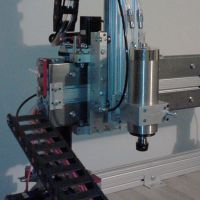
Next stepper motor installation.
These stepper motors didn't have a flat for the set screw so off to the grinder I went. Here is the result.
This will help keep the pulley anchored to the stepper motors shaft. From previous experiences in cnc machines this is a must
These stepper motors didn't have a flat for the set screw so off to the grinder I went. Here is the result.
This will help keep the pulley anchored to the stepper motors shaft. From previous experiences in cnc machines this is a must
- Attachments
-
My rostock build log http://forum.seemecnc.com/viewtopic.php?f=42&t=1228
Re: Another rostock max build
Next I loctited all the screws for the stepper motors and the set screws for the pulleys.
I started putting in the slot nuts for the extrusion and installed the bearings in there places. Installed the power supply.
So far still going smoothly with assembly. I then started putting together the cheapskates. This took the most time thus far because the u-joints required quite a bit of sanding to get them to spin freely. Then called it a night.
I started putting in the slot nuts for the extrusion and installed the bearings in there places. Installed the power supply.
My rostock build log http://forum.seemecnc.com/viewtopic.php?f=42&t=1228
Re: Another rostock max build
Make sure when you put the black plastic things (i forget what they are called) on the cheap skates you put the hole for the endstop screws on the same side. That way the screws will be the same for all of the cheap skates. Just cosmetic really but when you bend the tabs on the switches they will all be bent the same way.
Worst part is over, peeling the tape off of everything sucked.
Worst part is over, peeling the tape off of everything sucked.
-
Eaglezsoar
- ULTIMATE 3D JEDI
- Posts: 7159
- Joined: Sun Apr 01, 2012 5:26 pm
Re: Another rostock max build
You do this free hand because of your experience, do you have any tips on how to make the flats for those of us who are not so experienced?cambo3d wrote:Next stepper motor installation.
These stepper motors didn't have a flat for the set screw so off to the grinder I went. Here is the result.
This will help keep the pulley anchored to the stepper motors shaft. From previous experiences in cnc machines this is a must
I would hate to screw up a good stepper. The whole process of touching the shaft to a grinding wheel make me nervous and at 61 I don't have
the most steady hand. Any tips would be appreciated.
-
Polygonhell
- ULTIMATE 3D JEDI
- Posts: 2417
- Joined: Mon Mar 26, 2012 1:44 pm
- Location: Redmond WA
Re: Another rostock max build
You an do it with a handfile in a vice, but I would put some tape over the front and back of the motor to stop any filings getting into the bearings.Eaglezsoar wrote:You do this free hand because of your experience, do you have any tips on how to make the flats for those of us who are not so experienced?cambo3d wrote:Next stepper motor installation.
These stepper motors didn't have a flat for the set screw so off to the grinder I went. Here is the result.
This will help keep the pulley anchored to the stepper motors shaft. From previous experiences in cnc machines this is a must
I would hate to screw up a good stepper. The whole process of touching the shaft to a grinding wheel make me nervous and at 61 I don't have
the most steady hand. Any tips would be appreciated.
Printer blog http://3dprinterhell.blogspot.com/
-
MorbidSlowBurn

- Printmaster!
- Posts: 169
- Joined: Sun Mar 03, 2013 5:33 pm
Re: Another rostock max build
I haven't done the stepper mod myself. Is there any concern with the radial force of filing/grinding the shaft damaging the stepper?
-
Polygonhell
- ULTIMATE 3D JEDI
- Posts: 2417
- Joined: Mon Mar 26, 2012 1:44 pm
- Location: Redmond WA
Re: Another rostock max build
If you do it in a vice there is none, since the thing held in the vice is the shaft.MorbidSlowBurn wrote:I haven't done the stepper mod myself. Is there any concern with the radial force of filing/grinding the shaft damaging the stepper?
having said that I doubt unless you use a lot of force the radial load is going to hurt the stepper when using a grinder. The much bigger issue is keeping any filings out of the bearings.
I haven't bothered on mine, IME as long as the screws are tight, the pulleys don't slip, and experience tells me that screws on a flat are just as likely to come loose are screws on a shaft, so I'd use loctite on either.
Printer blog http://3dprinterhell.blogspot.com/