Another rostock max build
Re: Another rostock max build
(Sorry, I thought you where talking about the other ones. The camera is written in the Exif data.)
Re: Another rostock max build
Most of my photos were taken with the casio but not the close ups.aehM_Key wrote:(Sorry, I thought you where talking about the other ones. The camera is written in the Exif data.)
My rostock build log http://forum.seemecnc.com/viewtopic.php?f=42&t=1228
Re: Another rostock max build
Heat spreader (http://www.3dfabricationworks.com/rosto ... rades.html) mounted on top of the Onyx heat bed. In between the heat spreader and the onyx I laid a layer of thermal heatsink compound to help with heat transfer. edit: I had problems with the aluminum bowing, so it was removed later on.
Soldered everything underneath. 10awg Flexible silicone wire is no problem for tight spaces and its rated for 200 degrees Celsius. I should also mention that I used a 230/150 watt soldering iron to attach the larger 10 gauge wires to the heat bed.
Fit perfectly through the existing hole, no need to widen.
Solid state relay mounted behind my electronics door, wiring almost complete.
Last edited by cambo3d on Wed Apr 03, 2013 12:06 am, edited 1 time in total.
My rostock build log http://forum.seemecnc.com/viewtopic.php?f=42&t=1228
-
foshon

- Printmaster!
- Posts: 600
- Joined: Fri Mar 08, 2013 3:05 pm
- Location: Just to the right of SeeMeCNC
Re: Another rostock max build
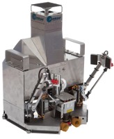
cambo3d wrote:Continuing into the morning hours.. I decided to mod my voitek power supply a little. Just to clean some wiring up and add few things. Here is a sneak peak. Dedicated 24v 31amp 750 watt Meanwell power supply and 25amp solid state relay for the Heated bed. To make sure my onyx gets to temp with the quickness.More to come later. I'm calling it a night.
Why not just use the 24v PS to power the RAMbo? It's rated for up to 36v. I have a MendelMax running on a 24v PS to power the linear y-axis upgrade kapton heater. It doesn't complain at all.
Purple = sarcasm
Please do a board search before posting your question, many have been answered with very time consuming detail already.
Please do a board search before posting your question, many have been answered with very time consuming detail already.
Re: Another rostock max build
Why not just use the 24v PS to power the RAMbo? It's rated for up to 36v. I have a MendelMax running on a 24v PS to power the linear y-axis upgrade kapton heater. It doesn't complain at all.[/quote]
The steppers that I have aren't rated for 24v and I wanted a dedicated supply for the heat bed.
The steppers that I have aren't rated for 24v and I wanted a dedicated supply for the heat bed.
My rostock build log http://forum.seemecnc.com/viewtopic.php?f=42&t=1228
-
MorbidSlowBurn

- Printmaster!
- Posts: 169
- Joined: Sun Mar 03, 2013 5:33 pm
Re: Another rostock max build
I believe was foshon is mentioning is that each power input has its own bus on the PCB. I can't confirm it because the wiki is down (http://reprap.org/wiki/Rambo). But if someone else more familiar with the board could confirm this it would be appreciated. Basically what the seperate bus means is that you can have 12V driving you steppers and 24V driving your heated bed with no conflict on the board. Just make sure you wire it up right..
Re: Another rostock max build
on rail is for the hotend(s) and fan(s)
and the 3rd rail is for the electronics itself (could also be powered via USB, depends on the jumper) and the steppers.
Re: Another rostock max build
I have already researched all this. while you could run everything separately, my rambo is powered by the 12v pc supply for a reason.MorbidSlowBurn wrote:I believe was foshon is mentioning is that each power input has its own bus on the PCB. I can't confirm it because the wiki is down (http://reprap.org/wiki/Rambo). But if someone else more familiar with the board could confirm this it would be appreciated. Basically what the seperate bus means is that you can have 12V driving you steppers and 24V driving your heated bed with no conflict on the board. Just make sure you wire it up right..
The reason why I didn't run the 24v through the rambo is because of its 15amp current limitation for the heat bed and possibly the connectors that it uses. . The onyx will draw around 20 amps at 24v. The other rails are rated at 5amps. If you used a 12v supply for the heat bed this would be okay because at 12v the onyx draws only 10amps.
so before you start thinking you can just throw anything in there. There are other factors to consider.
Last edited by cambo3d on Tue Mar 19, 2013 12:34 pm, edited 2 times in total.
My rostock build log http://forum.seemecnc.com/viewtopic.php?f=42&t=1228
Re: Another rostock max build
Will you change the firmware from PID-PWM to maybe a bang-bang controller for the heatbed, or how will it work with the relay?
Re: Another rostock max build
The heat bed output on the rambo will be used as the input to activate the SSR. I will be trying the default configuration first. I will see what works best but PID is what I was aiming for. Solid state relays are used quite often for heater circuits with pid controller.aehM_Key wrote:Will you change the firmware from PID-PWM to maybe a bang-bang controller for the heatbed, or how will it work with the relay?
My rostock build log http://forum.seemecnc.com/viewtopic.php?f=42&t=1228
Re: Another rostock max build
Sorry, I should have looked up earlier that a solid state relay isn't a relay 
English is not my first language and especially all these special technical terms are sometimes problematic
English is not my first language and especially all these special technical terms are sometimes problematic
-
foshon
- Printmaster!
- Posts: 600
- Joined: Fri Mar 08, 2013 3:05 pm
- Location: Just to the right of SeeMeCNC
Re: Another rostock max build
That's interesting. My RAMPS 1.4 runs on a single 24v supply. I was under the impression that the RAMbo was a one board replacement. Forgive my intrusion.cambo3d wrote:I have already researched all this. while you could run everything separately, my rambo is powered by the 12v pc supply for a reason.MorbidSlowBurn wrote:I believe was foshon is mentioning is that each power input has its own bus on the PCB. I can't confirm it because the wiki is down (http://reprap.org/wiki/Rambo). But if someone else more familiar with the board could confirm this it would be appreciated. Basically what the seperate bus means is that you can have 12V driving you steppers and 24V driving your heated bed with no conflict on the board. Just make sure you wire it up right..
The reason why I didn't run the 24v through the rambo is because of its 15amp current limitation for the heat bed and possibly the connectors that it uses. Also as stated before my steppers aren't rated for 24v.. The onyx will draw around 20 amps at 24v. The other rails are rated at 5amps. If you used a 12v supply for the heat bed this would be okay because at 12v the onyx draws only 10amps.
so before you start thinking you can just throw anything in there. There are other factors to consider.
Purple = sarcasm
Please do a board search before posting your question, many have been answered with very time consuming detail already.
Please do a board search before posting your question, many have been answered with very time consuming detail already.
Re: Another rostock max build
it is provided you keep everything within specs.
My rostock build log http://forum.seemecnc.com/viewtopic.php?f=42&t=1228
Re: Another rostock max build
more progress, ran the wires for the end stop switches, mounted the accessory fuse block.
My rostock build log http://forum.seemecnc.com/viewtopic.php?f=42&t=1228
Re: Another rostock max build
Today I decided to tackle an issue that I put off since i started working on the wiring.
After installing the build surface. It was not flat and seemed to have a bow in the middle. The aluminum that I was using as a heat spreader wasn't completely flat to begin with but I should have been able to flatten it out somewhat once I tightened the screws down but it actually got worse. I took everything off to check tolerances of the spacers they were all between 3.99mm and 3.97mm, I had two that measured over 4mm. To my surprise star spacer was also fairly flat.
This leads me to believe that the actual mounting surface of the rostock was the culprit and I need to solve this. I suspect its lies in how tight I have the frame assembled and the tolerances of laser cut parts.
I've been thinking of implementing some sort of bed leveling device to account for some of the inconsistency of the rostock frame.
My rostock build log http://forum.seemecnc.com/viewtopic.php?f=42&t=1228
Re: Another rostock max build
so here's a quick sketch of adjustable bed height/leveler
edit: bed leveler was removed later, it wasn't needed after getting my frame level.
Last edited by cambo3d on Wed Apr 03, 2013 12:08 am, edited 1 time in total.
My rostock build log http://forum.seemecnc.com/viewtopic.php?f=42&t=1228
-
Polygonhell
- ULTIMATE 3D JEDI
- Posts: 2417
- Joined: Mon Mar 26, 2012 1:44 pm
- Location: Redmond WA
Re: Another rostock max build
You could certainly do something like that, I have a similar setup on my MendelMax, if the bed itself isn't flat it won't help though.
If the surface is flat but not horizontal, unless it's miles out all that really matters is the head moves in the same plane as the bed.
If the surface is flat but not horizontal, unless it's miles out all that really matters is the head moves in the same plane as the bed.
Printer blog http://3dprinterhell.blogspot.com/
Re: Another rostock max build
the build surface bed itself is fairly flat, while not perfect. The whole build surface was even flatter after removing it from the rostock. Verified by comparing to a known flat surface.
95% of the unevenness seems to be coming from the rostock bed mounting platform itself. seems to dip down near the edges of the build platform, which makes sense for it to bow up in the middle when installed.
does anyone else have this problem? maybe this is what some people are experiencing with the onyx not being completely flat? because the uneveness of the mounting surface is causing it to bow up when mounted.
Last edited by cambo3d on Mon Mar 18, 2013 7:33 pm, edited 1 time in total.
My rostock build log http://forum.seemecnc.com/viewtopic.php?f=42&t=1228
Re: Another rostock max build
i tried to take photos of what im seeing. this is a straight edge on top of the platform. notice the gaps in the middle versus the outside ends.
edit: discovered later that the laser cut parts were out of alignment. seemecnc sent replacement parts.
edit: discovered later that the laser cut parts were out of alignment. seemecnc sent replacement parts.
- Attachments
-
-
-
Last edited by cambo3d on Wed Apr 03, 2013 12:09 am, edited 1 time in total.
My rostock build log http://forum.seemecnc.com/viewtopic.php?f=42&t=1228

Re: Another rostock max build
That's a bit odd. Mine was dead flat on assembly. I would have thought all of those internal base partitions would prevent it from bowing like that. Are all the screws snugged up? How's the bottom?
Sublime Layers - my blog on Musings and Experiments in 3D Printing Technology and Art
Start Here:
A Strategy for Successful (and Great) Prints
Strategies for Resolving Print Artifacts
The Eclectic Angler
Re: Another rostock max build
everything is snug up even with the partitions which troubles me, because that means the laser cut parts aren't square.mhackney wrote:That's a bit odd. Mine was dead flat on assembly. I would have thought all of those internal base partitions would prevent it from bowing like that. Are all the screws snugged up? How's the bottom?
hmmm..
My rostock build log http://forum.seemecnc.com/viewtopic.php?f=42&t=1228
Re: Another rostock max build
And what about the bottom, is it flat?
Sublime Layers - my blog on Musings and Experiments in 3D Printing Technology and Art
Start Here:
A Strategy for Successful (and Great) Prints
Strategies for Resolving Print Artifacts
The Eclectic Angler
Re: Another rostock max build
there is one spot that is out of place, shown in the picture, it seems this foot peg isn't touching the table, all the others are. its not the table because to matter where i rotate it. It doesn't touch. there seems to be a slight bow here at this spot. I noticed this before during the assembly but i didn't think this mattered. Everything is snug up to the partitions.mhackney wrote:And what about the bottom, is it flat?
My rostock build log http://forum.seemecnc.com/viewtopic.php?f=42&t=1228
Re: Another rostock max build
Well, i'm lil discouraged that my build has hit a snag but hopefully it can be fixed. Either with a some sanding or shimming or makeshift bed leveler or all..
to keep progress moving along I continued work on the hot end and the ujoints for that area. The assembly of the hot end ujoints actually went a lot faster then the cheap skate ujoints. Seemed like the hot end ujoints were a lot easier to sand and didn't require to much effort. Assembled the hot end tonight. took some pointers from the forum and used teflon tubing to insulate the thermistor and the resistor wires. Then laid a layer of high temp rtv on it. I wasn't going to use the rtv originally but it was about the only thing I could get locally so rtv it was. I'm still trying to get a hold of some resbond 920 to use later.
to keep progress moving along I continued work on the hot end and the ujoints for that area. The assembly of the hot end ujoints actually went a lot faster then the cheap skate ujoints. Seemed like the hot end ujoints were a lot easier to sand and didn't require to much effort. Assembled the hot end tonight. took some pointers from the forum and used teflon tubing to insulate the thermistor and the resistor wires. Then laid a layer of high temp rtv on it. I wasn't going to use the rtv originally but it was about the only thing I could get locally so rtv it was. I'm still trying to get a hold of some resbond 920 to use later.
- Attachments
-
-
My rostock build log http://forum.seemecnc.com/viewtopic.php?f=42&t=1228
Re: Another rostock max build
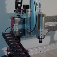
more work done today getting the rostock arms installed. This required an insane amount of sanding for a smooth fit. I can't tell you how many times I had to install, remove, sand and reinstall to check fit. definitely not installer friendly, I got to a point where I said enough was enough and just left them alone, I still think they could use more sanding for better, smoother motion. I started around noon and 3 hours later here's the result.
The hardware for my adjustable bed leveling idea came in today. Its nice to have mcmastercarr close by. I ordered the parts last night and they were here today.
more to come on this implementation, hopefully fixes my uneven rostock frame.
more to come on this implementation, hopefully fixes my uneven rostock frame.
Last edited by cambo3d on Tue Mar 19, 2013 6:33 pm, edited 1 time in total.
My rostock build log http://forum.seemecnc.com/viewtopic.php?f=42&t=1228