g.
Mhackney's Rostock Max
Re: Mhackney's Rostock Max
The cartridge heater and cartridge thermistor look to be an excellent combination. Maybe we could convince SeeMeCNC to produce a new heater block section that would allow these to be properly fitted without the aluminum foil kludge. I'd buy a few! (After some other knowledgeable person crafts the new tables!  )
)
g.
g.
Delta Power!
Defeat the Cartesian Agenda!
http://www.f15sim.com - 80-0007, The only one of its kind.
http://geneb.simpits.org - Technical and Simulator Projects
Defeat the Cartesian Agenda!
http://www.f15sim.com - 80-0007, The only one of its kind.
http://geneb.simpits.org - Technical and Simulator Projects

Re: Mhackney's Rostock Max
Thanks Carl. I know how to build a calibration table for these. I contacted the vendor to get specs but there are none. These devices have 2 wires so they should be easy enough to integrate. I looked for a shorter 10mm - 20mm version of these but haven't found them as yet.
I have to say that I am very happy with my cartridge heaters. I have 20 of them now! Am considering offering the extras for sale.
I have to say that I am very happy with my cartridge heaters. I have 20 of them now! Am considering offering the extras for sale.
Sublime Layers - my blog on Musings and Experiments in 3D Printing Technology and Art
Start Here:
A Strategy for Successful (and Great) Prints
Strategies for Resolving Print Artifacts
The Eclectic Angler
-
Eaglezsoar

- ULTIMATE 3D JEDI
- Posts: 7159
- Joined: Sun Apr 01, 2012 5:26 pm
Re: Mhackney's Rostock Max
Put the extras on your site. Be sure to keep some spares though, the past day or so proves you will need a few.mhackney wrote:Thanks Carl. I know how to build a calibration table for these. I contacted the vendor to get specs but there are none. These devices have 2 wires so they should be easy enough to integrate. I looked for a shorter 10mm - 20mm version of these but haven't found them as yet.
I have to say that I am very happy with my cartridge heaters. I have 20 of them now! Am considering offering the extras for sale.
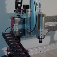
RAMPS
Well, I have the RAMPS 1.4 connected and started with a fresh Repetier host download from Git, I configured it from scratch for the MAX. I started with end stops and got those working, now I have motor control and the steppers sound smooth. The RAMPS supports 16 micro steps and came preconfigured that way. Now I just need to hook up the hot end and heated bed.
One thing about RAMPS - the connectors do not lock. I'm using the RAMBo connectors and they fit the RAMPS locations. But they pull out very easily. I need to decide if this is going to be my permanent solution or if I'll replace the RAMBo if I can't repair it. I'm also not happy with the connectors I assembled for the Rambo, there seems to be some fraying where the wire attaches to the crimp connector - probably from opening and closing the door the RAMBo was attached to too many times! You can see that here (attached to RAMPS):
[img]http://mhackney.zenfolio.com/img/s9/v87 ... 5524-4.jpg[/img]
Whatever I do, I will mount the board to a stationary location but make sure it can easily be removed for access.
I did get a nice wiring harness kit with the RAMPS that has the connectors professionally attached. I just don't relish re-wiring everything! The RAMPS does support dual extruders and RichRap has a cool mod to support 3 extruders. I also got these pre-assembled for $100 (bought 2) so they are pretty cost effective.
Sublime Layers - my blog on Musings and Experiments in 3D Printing Technology and Art
Start Here:
A Strategy for Successful (and Great) Prints
Strategies for Resolving Print Artifacts
The Eclectic Angler
Re: Mhackney's Rostock Max
do you use the right size crimper for those connector pins. they shouldn't look like that if you did. But I assume you prolly used what you had available
the purpose of the back end of the connector pin is to crimp down the insulation too and provide some strain relief. The middle part of the pin is actually where the bare wire gets crimped. If you have the correct tool, it does this in one shot.
the purpose of the back end of the connector pin is to crimp down the insulation too and provide some strain relief. The middle part of the pin is actually where the bare wire gets crimped. If you have the correct tool, it does this in one shot.
Last edited by cambo3d on Wed Apr 03, 2013 5:06 pm, edited 3 times in total.
My rostock build log http://forum.seemecnc.com/viewtopic.php?f=42&t=1228
Adjustable Build Plate design
Been collaborating in the background with Carl (aka Eaglezsoar) on a leveling build plate. The basic idea is to have a 3 point attachment to the Rostock base so the plate itself can be leveled accurately. Then, with the plate made from MIC-6 aluminum, flatness is all but guaranteed. The heating element - Onyx or even a silicone heater - is mounted underneath. Since the Mic-6 is 5/16" thick, the Onyx can be secured with screws into tapped holes in the plate. These are outside the build area. An optional support brace could be installed to minimize warping/sagging of the Onyx. Silicone adhesive could also be used to secure it or a silicone heater.
[img]http://mhackney.zenfolio.com/img/s2/v72 ... 4084-4.jpg[/img]
I made the threaded posts from M10x1 bolts. I've machined the heads flat and drilled and tapped for the #6-32 screw that will attach the MIC-6 plate to it. Since the pitch is 1mm per turn, precise and predictable adjustments can be made. I'll likely put washers between the nuts and Rostock base.
The only question is heat-up time. Thicker aluminum means more mass to heat. More mass means either more time or more power. We'll see, we'll see...
Sublime Layers - my blog on Musings and Experiments in 3D Printing Technology and Art
Start Here:
A Strategy for Successful (and Great) Prints
Strategies for Resolving Print Artifacts
The Eclectic Angler
Re: Mhackney's Rostock Max
my 3/8" mic 6 plate will be here to test out by this weekend, i'm hopeful this will solve some warping issues but looking around on other forums, Mic6 can also warp if not heated evenly. This only seems to be the case at higher temperatures though, nothing that we will be using for 3d printing so crossing my fingers.
My rostock build log http://forum.seemecnc.com/viewtopic.php?f=42&t=1228
It's (magnetic) play time
Just arrived via Priority Mail:
[img]http://mhackney.zenfolio.com/img/s2/v72 ... 4568-3.jpg[/img]
The cylinders are grade N52 - big boy magnets - 9.86 pound pull force (as compared to the lesser N42 at 7.96 pounds for the same size magnet). These are 3/8" D by 3/8" long. The steel bearings are not magnetized, 3/8" diameter. After reading specs on commercial units and doing some force calculations, these should do the trick. I am going the way the commercial units are made with a cylindrical magnet and a steel sphere for a number of reasons. I milled a quick "sheath" in Delrin to test the joint and it is smooth as silk and stays perfectly centered. I should have something to show over the weekend.
Sublime Layers - my blog on Musings and Experiments in 3D Printing Technology and Art
Start Here:
A Strategy for Successful (and Great) Prints
Strategies for Resolving Print Artifacts
The Eclectic Angler
Re: Mhackney's Rostock Max
Yeah I was thinking of something similar but it was expensive. http://www.ebay.com/itm/5-X-Magnetic-Ba ... 35c26fa972
I am looking forward to seeing what you come up with.
I am looking forward to seeing what you come up with.
The Xnaron Project http://xnaron.com find me also on youtube http://youtube.com/xnaron
3D Printers: Behemoth, Xnaron Prusa Bumblebee, Xnaron Prusa, Jolly Roger, MG Prusa, Rostock Max
Find me on IRC: #reprap, #seemecnc
3D Printers: Behemoth, Xnaron Prusa Bumblebee, Xnaron Prusa, Jolly Roger, MG Prusa, Rostock Max
Find me on IRC: #reprap, #seemecnc
Re: Mhackney's Rostock Max
Yes, the pre-made units are pricy and may not be the best size for this application. The Delrin will make a great low friction bearing surface and be easy to machine and light weight. One of my friends called me "Dr. Delrin" last weekend because I constantly promote the virtues of the material! I use it a lot in my reels too.
Sublime Layers - my blog on Musings and Experiments in 3D Printing Technology and Art
Start Here:
A Strategy for Successful (and Great) Prints
Strategies for Resolving Print Artifacts
The Eclectic Angler
Re: Mhackney's Rostock Max
How are you planning to hold the balls? Are you drilling into them? I'm thinking you are putting the magnet into a delrin thingy with a socket in it machined to fit the ball?mhackney wrote:Yes, the pre-made units are pricy and may not be the best size for this application. The Delrin will make a great low friction bearing surface and be easy to machine and light weight. One of my friends called me "Dr. Delrin" last weekend because I constantly promote the virtues of the material! I use it a lot in my reels too.
The Xnaron Project http://xnaron.com find me also on youtube http://youtube.com/xnaron
3D Printers: Behemoth, Xnaron Prusa Bumblebee, Xnaron Prusa, Jolly Roger, MG Prusa, Rostock Max
Find me on IRC: #reprap, #seemecnc
3D Printers: Behemoth, Xnaron Prusa Bumblebee, Xnaron Prusa, Jolly Roger, MG Prusa, Rostock Max
Find me on IRC: #reprap, #seemecnc
RAMPS Ramblings
I just feel compelled to add some commentary on my RAMPS excursion...
The RAMPS controller has been around for a while (it is in version 1.4) and thoroughly tested and supported by the main firmwares out there. I was able to use the RAMPS connector that came with the LCD display to hook it up to the RAMPS board with no hassles. Then, configuration for the RAMPS was about as painless as I could imagine. Even the LCD came up and displayed "Rostock MAX" the first time. It seems the RAMBo causes a lot of unnecessary pain because of its newness and unhardened support in the firmwares out there. Hopefully this will stabilize in the near future but it was quite refreshing to work with a board and firmware that have been seasoned!
The RAMPS controller has been around for a while (it is in version 1.4) and thoroughly tested and supported by the main firmwares out there. I was able to use the RAMPS connector that came with the LCD display to hook it up to the RAMPS board with no hassles. Then, configuration for the RAMPS was about as painless as I could imagine. Even the LCD came up and displayed "Rostock MAX" the first time. It seems the RAMBo causes a lot of unnecessary pain because of its newness and unhardened support in the firmwares out there. Hopefully this will stabilize in the near future but it was quite refreshing to work with a board and firmware that have been seasoned!
Sublime Layers - my blog on Musings and Experiments in 3D Printing Technology and Art
Start Here:
A Strategy for Successful (and Great) Prints
Strategies for Resolving Print Artifacts
The Eclectic Angler
Re: Mhackney's Rostock Max
xnaron wrote:How are you planning to hold the balls?
The magnet will be in a Delrin cylinder. One end will be milled with a 3/8" ball mill (an extra sharp one for the job) and the other will have a 3/8" hole for the magnet. It will be "drilled" with an endmill so the hole is flat bottomed so the magnet can get as close to the ball in the socket as possible - 1mm should be sufficient based on my calculations.
The ball will be drilled and tapped with a stud inserted. I'll likely fix the ball to the carriage and delta head since they have the lowest profile. The magnet cylinder will be attached to the rods. I am currently looking at aluminum arrow shafts. These things are incredibly stiff - much stiffer than carbon fiber tube of similar dimensions.
Sublime Layers - my blog on Musings and Experiments in 3D Printing Technology and Art
Start Here:
A Strategy for Successful (and Great) Prints
Strategies for Resolving Print Artifacts
The Eclectic Angler
Re: Mhackney's Rostock Max
LOL! I thought that sounded funny as I typed it.mhackney wrote:xnaron wrote:How are you planning to hold the balls?Decorum prevents me from answering that question!
I have built many tri, quad and hexa copters and found this http://www.hobbyking.com/hobbyking/stor ... 750mm.html
to be exceptionally strong and extremely light. Dimensionally it would be similar in size to the rmax arms. It actually looks much nicer than what they picture. It has a nice carbon fiber pattern.
The Xnaron Project http://xnaron.com find me also on youtube http://youtube.com/xnaron
3D Printers: Behemoth, Xnaron Prusa Bumblebee, Xnaron Prusa, Jolly Roger, MG Prusa, Rostock Max
Find me on IRC: #reprap, #seemecnc
3D Printers: Behemoth, Xnaron Prusa Bumblebee, Xnaron Prusa, Jolly Roger, MG Prusa, Rostock Max
Find me on IRC: #reprap, #seemecnc
-
MorbidSlowBurn

- Printmaster!
- Posts: 169
- Joined: Sun Mar 03, 2013 5:33 pm
Re: Mhackney's Rostock Max
I have a similar idea with the magnets and balls. But I was planning on printing the sockets for the magnets. Hopefully by the end of the weekend I will have a sample to post. My parts are due in tomorrow.
-
Polygonhell
- ULTIMATE 3D JEDI
- Posts: 2417
- Joined: Mon Mar 26, 2012 1:44 pm
- Location: Redmond WA
Re: Mhackney's Rostock Max
So your intent is to machine the cups in Delrin, and mount the magnets behind them?mhackney wrote:Yes, the pre-made units are pricy and may not be the best size for this application. The Delrin will make a great low friction bearing surface and be easy to machine and light weight. One of my friends called me "Dr. Delrin" last weekend because I constantly promote the virtues of the material! I use it a lot in my reels too.
That was my first thought, my concern was whether the magnets would keep the ball seated though the delrin, but 10lbs is a lot of holding force.
Printer blog http://3dprinterhell.blogspot.com/
Re: Mhackney's Rostock Max
Exactly. Delrin is a nonpermeable material - meaning it has no significant effect on magnetic fields. So the design consideration comes down to distance of the magnet to the ball. A gap of 1mm at the closest (and then decreasing from there) can be estimated. Here is an online calculator. At a distance of 1mm, assuming a flat plate of steel, the pull force drops to 3.69 pounds. Decrease that to .5mm and you get 5.39 pounds.
Also consider, the ball is nestled in a cradle of Delrin that minimizes the possibility of dislodging sideways. In fact, a cradle at least 25% of the diameter of the bearing is needed to insure accurate centering. With a cradle like this, considerable sideways force is required to dislodge. Even gripping the ball and trying to pull it free requires a lot of force.
Also consider, the ball is nestled in a cradle of Delrin that minimizes the possibility of dislodging sideways. In fact, a cradle at least 25% of the diameter of the bearing is needed to insure accurate centering. With a cradle like this, considerable sideways force is required to dislodge. Even gripping the ball and trying to pull it free requires a lot of force.
Sublime Layers - my blog on Musings and Experiments in 3D Printing Technology and Art
Start Here:
A Strategy for Successful (and Great) Prints
Strategies for Resolving Print Artifacts
The Eclectic Angler
-
Polygonhell
- ULTIMATE 3D JEDI
- Posts: 2417
- Joined: Mon Mar 26, 2012 1:44 pm
- Location: Redmond WA
Re: Mhackney's Rostock Max
I guess you could probably get down into the 0.005in range relatively easily. I'll be interested in how much force you really have, because the percentage of the sphere in close contact is going to be small.mhackney wrote:Exactly. Delrin is a nonpermeable material - meaning it has no significant effect on magnetic fields. So the design consideration comes down to distance of the magnet to the ball. A gap of 1mm at the closest (and then decreasing from there) can be estimated. Here is an online calculator. At a distance of 1mm, assuming a flat plate of steel, the pull force drops to 3.69 pounds. Decrease that to .5mm and you get 5.39 pounds.
Also consider, the ball is nestled in a cradle of Delrin that minimizes the possibility of dislodging sideways. In fact, a cradle at least 25% of the diameter of the bearing is needed to insure accurate centering. With a cradle like this, considerable sideways force is required to dislodge. Even gripping the ball and trying to pull it free requires a lot of force.
UHMWPE would be a lot cheaper than delrin and probably comparable in this application.
Printer blog http://3dprinterhell.blogspot.com/
Re: Mhackney's Rostock Max
The call me "Dr. Delrin"!
The cost of the material is inconsequential, there is so little of it. Delrin machines like a dream and I have years of experience using it. I also have lots of it in my shop already and no UNHMWPE. AND, it comes in black!
Like I said above, I've already made one of these cups with about .1mm of clearance. I have a difficult time grasping and removing the ball. Not quantitative, I know, but there is a lot of force there.
Sublime Layers - my blog on Musings and Experiments in 3D Printing Technology and Art
Start Here:
A Strategy for Successful (and Great) Prints
Strategies for Resolving Print Artifacts
The Eclectic Angler

Re: Mhackney's Rostock Max
Steel balls? Arrow shafts? Better hope you don't drop one on your borosilicate glass, or crash into the build plate due to a software glitch. That could get expensive.
- dan
- dan
Re: Mhackney's Rostock Max
Did you order stainless steel balls or just hardened chrome steel balls? How are you planning to drill into them? Assuming center was found I was thinking of using a vbit to spot the hole and then drill it out with the correct bit. I thought about also doing it on the lathe if I could get the ball chucked up.
The Xnaron Project http://xnaron.com find me also on youtube http://youtube.com/xnaron
3D Printers: Behemoth, Xnaron Prusa Bumblebee, Xnaron Prusa, Jolly Roger, MG Prusa, Rostock Max
Find me on IRC: #reprap, #seemecnc
3D Printers: Behemoth, Xnaron Prusa Bumblebee, Xnaron Prusa, Jolly Roger, MG Prusa, Rostock Max
Find me on IRC: #reprap, #seemecnc
Re: Mhackney's Rostock Max
Most stainless is not magnetic so these are steel. I will spot them and drill. I can do this on either the lathe (with a 5C chuck) or mill (also a 5C chuck). Balls this size can be drilled easily so I don't anticipate a challenge.
Sublime Layers - my blog on Musings and Experiments in 3D Printing Technology and Art
Start Here:
A Strategy for Successful (and Great) Prints
Strategies for Resolving Print Artifacts
The Eclectic Angler
Re: Calibration Pyramid and info
Do you KISSlicer to just generate the G-code and then export to repetier or also print?mhackney wrote:Just wanted to capture this in my build thread:
KISSlicer 1.1 RC2 (released today on Mac)
.5mm skin
2 loops
50% infill
.55mm extrusion width and infill extrusion width
.25mm layer thickness
1.0 / 45° Jitter (new feature as of today, just learning how to use it!)
195°C nozzle
60°C heated bed on blue tape
10mm prime/suck
5mm wipe
20mm/s speed
1.5mm min jump
5mm trigger
On the printer side you can get the accel and extruder speeds on my EEPROM screen shot: stepper digipot 175
Let me know if I missed anything!
Oh yeah, while it was printing I was dancing up and down with a counter clock wise spin!
Re: Mhackney's Rostock Max
I don't understand the question aeroula.
Sublime Layers - my blog on Musings and Experiments in 3D Printing Technology and Art
Start Here:
A Strategy for Successful (and Great) Prints
Strategies for Resolving Print Artifacts
The Eclectic Angler
-
elqisqeyano

- Printmaster!
- Posts: 256
- Joined: Sat Mar 30, 2013 1:29 pm
- Location: Franklin County Ohio
Re: Mhackney's Rostock Max
Can 2 of them be used to replace both factory resistors sent by Seemecnc? Or only 1 is allowed to be used at a time? I'd like to put 2 of them on my hot end. Take out the 2 resistors and replace them with these clean ones. Does any one know if 2 of them can be put on the hot end at the same time just like with the 2 factory resistors?Flateric wrote:http://www.ebay.ca/itm/221168698861?ssP ... 757wt_1398
Have you seen these yet? Looks like a nicer cleaner way of heating the hotend. Less chance of shorting out too.