I can flick all my u joints with the tip of my finger and they will keep spinning on there own. Arms freely move no friction there.MorbidSlowBurn wrote:When you checked your arms did you have each joint fully assembled? How much the screw are tightened make a huge impact on friction of the joint. I personally worked a single end of each arm completely before moving to the next. My measure of a good joint was when an arm was connected only at one end it would hang straight down under gravity for both vertical and side to side motions. I tested this way for all 12 joints. I put the arm in the various positions at different heights to check if there was friction at any orientation of the angle.
Looking at your print it does look like there is still friction.
To be thorough did you also calibrate your extruder based on the sticky that polygonhell wrote? Has some impact on fill completion but based on other posts and experience a majority of your gaps appear to be from friction.
Another rostock max build
Re: Another rostock max build
Last edited by cambo3d on Fri Mar 29, 2013 12:52 pm, edited 2 times in total.
My rostock build log http://forum.seemecnc.com/viewtopic.php?f=42&t=1228
Re: Another rostock max build
this was after after extruder calibration, before i printed the forth calibration cube above.
My rostock build log http://forum.seemecnc.com/viewtopic.php?f=42&t=1228
-
Polygonhell
- ULTIMATE 3D JEDI
- Posts: 2417
- Joined: Mon Mar 26, 2012 1:44 pm
- Location: Redmond WA
Re: Another rostock max build
The 20x20x10 cube looks good, but from the other cube you have some backlash somewhere, it could be in the arm joints and it could be in the belts.
Check the belts the most likely damage is going to be at the stepper when the head is near 0. That's on the inside of the tower about 1/3 of the way up when homed.
Be careful not to go too tight with the belts, you can break the internal fibers at which point they are just very springy and introduce additional backlash. I did this trying to chase an issue where one of my belts was damaged in a head crash, initially I had a small amount of backlash introduced by the damaged belt, which I made considerably worse by over tightening all the belts, ended up replacing them all.
MHackney's test print isn't a bad way to try and narrow this down, I personally print a large triangle with edges aligned with the pillars to try and determine which pillars are affected, you have to watch the infill go down and figure out which pillar is more likely responsible.
Printer blog http://3dprinterhell.blogspot.com/
Re: Another rostock max build
i haven't checked my belts. I need to check those I did have a head crash, because I forgot the set the eeprom heights correctly on initial calibration.
i'll check the belts today. hopefully thats the issue.
i'll check the belts today. hopefully thats the issue.
My rostock build log http://forum.seemecnc.com/viewtopic.php?f=42&t=1228
Re: Another rostock max build
I took the belts off to check, there is some fraying but the teeth are still intact, i ordered another set to replace anyway.
bad section
good section
bad section
My rostock build log http://forum.seemecnc.com/viewtopic.php?f=42&t=1228
Re: Another rostock max build
after seeing apachexmd's problem almost similar to mine.
I decided to take my rostock apart, I found the same issue he had. contacting seemecnc right away!
no matter where i rotate this, it's always off alignment. I'm gonna do some further investigating. I believe this is part of my calibration issues.
after taking a couple more measurements and comparing i'm convinced my frame is off alignment. Wished i would have done this before I assembled it.
EDIT: 4/4/2013
THIS IS MAKES A DIFFERENCE IN HOW LEVEL AND SQUARE THE MACHINE IS ON FINAL ASSEMBLY. I WOULD SUGGEST TO ANYONE BEFORE ACTUALLY ASSEMBLING THE MACHINE, TO CHECK FOR ALIGNMENT OF THE LASER CUT PARTS. I'M WAITING FOR ANOTHER FULL FRAME KIT FROM TRICKLASER.COM. TO SEE IF THEIR KIT IS ANY BETTER; IF NOT, I'LL HAVE TO COME UP WITH SOMETHING TO KEEP THE BASE FLAT/LEVEL OR JUST REMAKE THE BASE ALL TOGETHER ON MY CNC ROUTER.
assembly suggestions:
check the alignment of all parts, especially all critical to alignment of the towers and the bed platform. the top plate needs to be aligned with the top of the bottom base plate (the labeled circular plate), I found that these two parts are not symmetrical, when I compared the extrusion alignment slots in the melamine, I found they were off unless you rotate it to a some what matching position, Even then you still have to sand a little for an even fit.My first kit was way off, replacement parts were better but still not symmetrical.
For the bed platform, make sure that all the individual vertical partitions are all the same height, if not, this will cause warping of your bed platform when tightening down the assembly screws.
My power supply retainer partition was way off, to a point causing extreme warping. Not only was this partition not the same height, slots on the partition needed to be sanded smaller to prevent it from warping the other partitions. there is major discrepancy in the fit of this particular piece. it is not dimensioned correctly. unfortunately this part was not included in my seemecnc care package of replacement parts. my workaround for this is to just leave it in the slots not tightened down, the slots itself will keep the partition from coming out. I would remove this altogether but it keeps the power supply in place.
I decided to take my rostock apart, I found the same issue he had. contacting seemecnc right away!
no matter where i rotate this, it's always off alignment. I'm gonna do some further investigating. I believe this is part of my calibration issues.
EDIT: 4/4/2013
THIS IS MAKES A DIFFERENCE IN HOW LEVEL AND SQUARE THE MACHINE IS ON FINAL ASSEMBLY. I WOULD SUGGEST TO ANYONE BEFORE ACTUALLY ASSEMBLING THE MACHINE, TO CHECK FOR ALIGNMENT OF THE LASER CUT PARTS. I'M WAITING FOR ANOTHER FULL FRAME KIT FROM TRICKLASER.COM. TO SEE IF THEIR KIT IS ANY BETTER; IF NOT, I'LL HAVE TO COME UP WITH SOMETHING TO KEEP THE BASE FLAT/LEVEL OR JUST REMAKE THE BASE ALL TOGETHER ON MY CNC ROUTER.
assembly suggestions:
check the alignment of all parts, especially all critical to alignment of the towers and the bed platform. the top plate needs to be aligned with the top of the bottom base plate (the labeled circular plate), I found that these two parts are not symmetrical, when I compared the extrusion alignment slots in the melamine, I found they were off unless you rotate it to a some what matching position, Even then you still have to sand a little for an even fit.My first kit was way off, replacement parts were better but still not symmetrical.
For the bed platform, make sure that all the individual vertical partitions are all the same height, if not, this will cause warping of your bed platform when tightening down the assembly screws.
My power supply retainer partition was way off, to a point causing extreme warping. Not only was this partition not the same height, slots on the partition needed to be sanded smaller to prevent it from warping the other partitions. there is major discrepancy in the fit of this particular piece. it is not dimensioned correctly. unfortunately this part was not included in my seemecnc care package of replacement parts. my workaround for this is to just leave it in the slots not tightened down, the slots itself will keep the partition from coming out. I would remove this altogether but it keeps the power supply in place.
- Attachments
-
-
-
-
-
-
Last edited by cambo3d on Thu Apr 04, 2013 5:04 pm, edited 11 times in total.
My rostock build log http://forum.seemecnc.com/viewtopic.php?f=42&t=1228
-
Jimustanguitar

- ULTIMATE 3D JEDI
- Posts: 2608
- Joined: Sun Mar 31, 2013 1:35 am
- Location: Notre Dame area
- Contact:
Re: Another rostock max build
cambo3d wrote: Installed and ready for cable connections. On the adapter as viewed from my photo. The top 10 pin header is your A connector from the lcd ( "A" connector meaning left connector on lcd) and the bottom is your B connector from the lcd.
[
I hope they silk screen A and B on the next version of the adapter. Maybe on the back of the LCD too since there isn't documentation that says so. It makes sense that A is on top, but you never know. I'd hate to burn up a component by guessing.
Re: Another rostock max build
this is the reply i got from john at seemecnc "If you connect A to the top and the LCD doesn't light up, then switch them around. It doesn't hurt them to be connected backwards, just the LCD will not light up"
My rostock build log http://forum.seemecnc.com/viewtopic.php?f=42&t=1228
Re: Another rostock max build
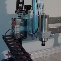
I'm going to try integrate these hall effect switches into my reassembly. The limit switches and the screws are bit finicky when it comes time to adjust z height. I'm hoping these will be better, accuracy wise. I had these in my electronics pile from other projects. http://sccatalog.honeywell.com/pdbdownl ... 13A-10.pdf
Last edited by cambo3d on Thu May 09, 2013 1:14 am, edited 1 time in total.
My rostock build log http://forum.seemecnc.com/viewtopic.php?f=42&t=1228
-
Eaglezsoar

- ULTIMATE 3D JEDI
- Posts: 7159
- Joined: Sun Apr 01, 2012 5:26 pm
Re: Another rostock max build
Did you check around for a source for the belts and could share with us or did you get them from Seemecnc? I was just wondering because itcambo3d wrote:I took the belts off to check, there is some fraying but the teeth are still intact, i ordered another set to replace anyway.
bad section good section
would be nice to keep a spare set on hand.
Carl
Re: Another rostock max build
im getting them from seemecnc
My rostock build log http://forum.seemecnc.com/viewtopic.php?f=42&t=1228
-
MorbidSlowBurn

- Printmaster!
- Posts: 169
- Joined: Sun Mar 03, 2013 5:33 pm
Re: Another rostock max build
kudos, to seemecnc, they are shipping a replacement set for my misaligned parts. I ordered a frame set from tricklaser.com to try out also, Might actually end up with 2 rostocks after i'm done building..
Reflecting back on ideas that I put a hold to, I've been working on modified upper idler belt tensioner mounts so I can get my turnbuckle idea to work. http://forum.seemecnc.com/viewtopic.php ... 8&start=90 Still plan to use off the shelf parts. Stock mount works but if you tighten the screw to much is damages the melamine. With this setup it shouldn't do that.
If anyone wants a set. I'll see if can get someone to cut a larger run of these after I've tested them. I can put together a plug and play kit or you can have someone laser cut a set for you. I'll post the final dxf file here and other parts needed. Once everything is tested.
Reflecting back on ideas that I put a hold to, I've been working on modified upper idler belt tensioner mounts so I can get my turnbuckle idea to work. http://forum.seemecnc.com/viewtopic.php ... 8&start=90 Still plan to use off the shelf parts. Stock mount works but if you tighten the screw to much is damages the melamine. With this setup it shouldn't do that.
Last edited by cambo3d on Thu Apr 04, 2013 1:18 am, edited 6 times in total.
My rostock build log http://forum.seemecnc.com/viewtopic.php?f=42&t=1228
Re: Another rostock max build
Good for seemecnc! Sucks that you have to build it all over again but at least it should be flat and straight this time around. I like all the tensioner ideas too. Keep it up! (so i can steal them 
-
Eaglezsoar
- ULTIMATE 3D JEDI
- Posts: 7159
- Joined: Sun Apr 01, 2012 5:26 pm
Re: Another rostock max build
Do you have any ideas of what to make the new part from? I would be interested in purchasing a set if they become available.cambo3d wrote:kudos, to seemecnc, they are shipping a replacement set for my misaligned parts. I ordered a frame set from tricklaser.com to try out also, Might actually end up with 2 rostocks after i'm done building..
Reflecting back on ideas that I put a hold to, I've been working on modified drawings for the upper idler belt tensioner mounts so I can get my turnbuckle idea to work. http://forum.seemecnc.com/viewtopic.php ... 8&start=90 Still plan to use off the shelf parts. Stock mount works but if you tighten the screw to much is damages the melamine. With this setup it shouldn't do that. I'll see if can get someone to cut a larger run of these so if anyone wants a set, I can get a plug in play kit together.
Carl
Re: Another rostock max build
same melamine as the rostock
My rostock build log http://forum.seemecnc.com/viewtopic.php?f=42&t=1228
-
Eaglezsoar
- ULTIMATE 3D JEDI
- Posts: 7159
- Joined: Sun Apr 01, 2012 5:26 pm
Re: Another rostock max build
Why would this new configuration not be damaged as you tighten the screw if it is made from the same material?cambo3d wrote:same melamine as the rostock
Re: Another rostock max build
with the stock setup you have to tighten down the screw against the melamine in order to keep the idler tensioner in place and it damages the melamine if you over tighten it. With this setup, you actually have to keep the screws that hold the idler tensioner loose so you can adjust the tension via the turnbuckle.
here's what mine looks like.
here's what mine looks like.
My rostock build log http://forum.seemecnc.com/viewtopic.php?f=42&t=1228
Re: Another rostock max build
teaser ... another add on i'm working on..
Haven't decided if I will use all 6 or just 3, these are some pretty blinding leds at 1 watt a piece!! I'll be adding a variable pot for adjustable light intensity. I'm using aluminum because it doubles as a mounting plate and heat sink. Mount uses stock mounting hole locations. plug-n-play design
milled aluminum led mounting plate and leds
Last edited by cambo3d on Tue Apr 02, 2013 11:47 pm, edited 4 times in total.
My rostock build log http://forum.seemecnc.com/viewtopic.php?f=42&t=1228

Re: Another rostock max build
Gee, that looks like it'd be a quick print. Does it need to be aluminum?
- dan
- dan
Re: Another rostock max build
went to home depot today and while I was there I picked some of this ptfe dry lube in a spray can. Placed it on all my joints and the difference was night and day. Might even work good for the moving parts in the extruder to get rid of some of the squeaks, just dont get it on the filament roller.
My rostock build log http://forum.seemecnc.com/viewtopic.php?f=42&t=1228
Better way to get your extrusions aligned properly
I thought I'd share this with everyone since there has been some confusion on how much gap to have between the extrusion and the frame. I am in the process of reassembly and I might as well show you how i did it. Following procedures assume you have checked your laser cut parts and all are aligned properly.
for this to work part numbers 68351 (base table top), 68368 (top support plate), and 68369 (TOP IDLER MOUNTS, check hole alignment) need to be perfectly the same. Sand if you need to square them up. photo shown below of the two circular plates stacked on top of each other. yes i know my spelling is wrong.
Once your ready to install the aluminum extrusions here's how to get them perfectly the same height. installation bolts are installed snug but not tightened yet at this point. If you dont have an extra t-slot nut, use whatever that fits in that hole.
WHATEVER, you used here make sure that the material is snug against the extrusion. (note: this assumes that all your extrusions are the same length also, check before you proceed)
install the screw that holds the top support plate to the extrusion, its one single screw held in by an anchor nut on the other side. (you can do this step before hand also, i just chose to put it here in the write up)
Once the above has been done. Grab the feeler gauges, flat automotive type, you get these from any autoparts store, I got mine from advance auto parts.
use the feeler gauge as space gauge. Press the extrusion against it and tighten up the bolts for the bottom. (select a feeler gauge that will give you the same space for the bottom and the top, mine came out to be .024in or .610mm)
next go to the top, and do the same thing. once you have the space correct tighten down the bolts.
Now repeat this procedure for the other two towers.
Once done all three towers will be at the same height and perpendicular to each other. Oh yeah, DONT FORGET TO REMOVE YOUR ALIGNMENT TOOLS (IE. T-SLOT NUT THAT YOU USED TO ALIGN THE BOTTOM AND THE MATERIAL YOU USED TO ALIGN THE TOP
for this to work part numbers 68351 (base table top), 68368 (top support plate), and 68369 (TOP IDLER MOUNTS, check hole alignment) need to be perfectly the same. Sand if you need to square them up. photo shown below of the two circular plates stacked on top of each other. yes i know my spelling is wrong.
install the screw that holds the top support plate to the extrusion, its one single screw held in by an anchor nut on the other side. (you can do this step before hand also, i just chose to put it here in the write up)
use the feeler gauge as space gauge. Press the extrusion against it and tighten up the bolts for the bottom. (select a feeler gauge that will give you the same space for the bottom and the top, mine came out to be .024in or .610mm)
Once done all three towers will be at the same height and perpendicular to each other. Oh yeah, DONT FORGET TO REMOVE YOUR ALIGNMENT TOOLS (IE. T-SLOT NUT THAT YOU USED TO ALIGN THE BOTTOM AND THE MATERIAL YOU USED TO ALIGN THE TOP
Last edited by cambo3d on Fri Apr 05, 2013 3:25 pm, edited 8 times in total.
My rostock build log http://forum.seemecnc.com/viewtopic.php?f=42&t=1228
Re: Another rostock max build
I recommend to measure the height.
Re: Another rostock max build
it is measured, they all measured the same. And you can do this once your done aligning all the towers just to double check.
Everything should measure the same if all your laser cut parts are aligned like I stated earlier.
Everything should measure the same if all your laser cut parts are aligned like I stated earlier.
Last edited by cambo3d on Fri Apr 05, 2013 2:32 am, edited 1 time in total.
My rostock build log http://forum.seemecnc.com/viewtopic.php?f=42&t=1228
Re: Another rostock max build
Ok, great. I aligned with the marks and it was few mm off, when measuring.