aehM_Key's Rostock Max Upgrades

Start your own build thread so others can see how it's going, and even help out!
Post Reply
User avatar
aehM_Key
Printmaster!
Posts: 200
Joined: Sun Nov 18, 2012 4:46 am
Location: Germany
Contact:

aehM_Key's Rostock Max Upgrades

Post by aehM_Key »

Hello!

I did a few modifications to my Rostock Max. Most of them are inspired by some of you guys - thanks for your input!

I'm not sure if every of this upgrade is necessary to get a better print quality, longer machine lasting or better operation - I just like handicraft work :)

Let's get started!

Lights
The wires are going through one aluminium rail.
DSCF2604.jpg
Extruder stiffener
Made of an allen wrench - I have plenty of them due to Ikea ;)
Now it's possible to adjust the position of the gear, so it is in the center of the two other gears.
DSCF2614.jpg
Connectors
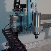
I added 2 pairs of D-Sub connectors for easier removal of the extruder-unit. One is for the hotend the other one for the extruder stepper. The connectors are screwed together for save operation.
DSCF2607.jpg
Emergency switch
It is connected to the green wire of the PC power supply and switches off the power for the stepper motors (and hotend).
DSCF2603.jpg
Switches
The small one switches the lights the large one the power to the heatbed.
I also screwed the LCD face plate above the display to the LCD standoff plates. The screws are going through the holes in the PCB of the display. I added a nice aluminium knob.
DSCF2620.jpg
Heat sinks
There where places to put heat sinks on the backside of the Rambo, so I put some there ;) Probably not necessary.
DSCF2612.jpg
Onyx backside insulation
I added some aluminium foil to the back of the Onyx to minimize heat radiation.
DSCF2615.jpg
Table insulation
I added also some aluminium foil to the top of the table. With this two foils I could significantly increase the heatbed temperature (with the original underpowered power supply).
You can see in the picture also a small chamfer for the wires and how I soldered the wires to the back of the heatbed pointing inwards.
DSCF2616.jpg
Automotive fuses
I replaced the fuses for the heatbed and hotend with automotive ones.
DSCF2618.jpg
Aluminum heat dissipator plate
Like Mhackneys, just without the cutout for electronics pads. (Because I soldered them to the back side.)
Got it for 10€ water cut from a local. It was important to be precise with the holes for the screws, but because there are six of them, it was easy with a pair of compasses. ;)
I replaced the screws with metric ones. (Had to change the t-nuts as well.)
I'm using six 9mm paper clips (the original ones are 7mm).
DSCF2621.jpg
Last edited by aehM_Key on Sat Mar 09, 2013 4:02 pm, edited 3 times in total.
User avatar
aehM_Key
Printmaster!
Posts: 200
Joined: Sun Nov 18, 2012 4:46 am
Location: Germany
Contact:

Re: aehM_Key's Rostock Max Upgrades

Post by aehM_Key »

Spool holder extension
My spools where not fitting, so I added some longer screws (guess what, metric ones ;) ) and spacers.
DSCF2622.jpg
Additional 24W 300W power supply
I decided to add an additional power supply just for the heatbed. It's running at it's limits just with the heatbed and I didn't want to have unstable voltage for the steppers depending on the heatbed load, so I decided to let the original PC power supply in place (for the steppers and hotend). I cut out the opening for the fan, added rubber decouplers and a potentiometer to control the fan. I added also small feet so I'm not covering the air openings. The supply fit's just behind the LCD door.
DSCF2627.jpg
12V step down voltage regulator
Now I have light even with the emergency switch hit. But the biggest advantage is, that the lights are not flickering when the hotend/heatbed doing their PWM.
The black foam is to guide the air which is coming out of the power supply through the finger hole of the door.
DSCF2625.jpg
IEC socket and central switch
..to connect both power supplies.
DSCF2624.jpg
Endswitch screws
I turned the screws upside down and filed them planar.
DSCF2630.jpg
Overview picture
..with unsorted background ;)
DSCF2628.jpg
Don't hesitate to ask if you need more detailed information!

Kind regards,
Markus
Last edited by aehM_Key on Sat Mar 09, 2013 4:11 pm, edited 2 times in total.
Polygonhell
ULTIMATE 3D JEDI
Posts: 2417
Joined: Mon Mar 26, 2012 1:44 pm
Location: Redmond WA

Re: aehM_Key's Rostock Max Upgrades

Post by Polygonhell »

For the drivers, they are designed for heats sinks on the back side not on top of the chip, so you did the right thing.
User avatar
cambo3d
ULTIMATE 3D JEDI
Posts: 1057
Joined: Thu Feb 07, 2013 10:03 pm
Location: Florida

Re: aehM_Key's Rostock Max Upgrades

Post by cambo3d »

is your whole electronics setup run off of 24v? The steppers that seemecnc uses are rated at 12v. Are you noticing them getting any hotter at 24v if so?. I'm asking because I might do 24v setup myself but might run dedicated power to the onyx and seperate for the rest.

edit: nevermind i see u used a converter and the original power supply. looks good
geneb
ULTIMATE 3D JEDI
Posts: 5358
Joined: Mon Oct 15, 2012 12:47 pm
Location: Graham, WA
Contact:

Re: aehM_Key's Rostock Max Upgrades

Post by geneb »

I really like how you handled the spool holder! I've got some PLA from RainBot3D and they're too wide for the existing structure. I may get some new screws and print me up some spacers! :D

g.
Delta Power!
Defeat the Cartesian Agenda!
http://www.f15sim.com - 80-0007, The only one of its kind.
http://geneb.simpits.org - Technical and Simulator Projects
User avatar
Av8r RC
Printmaster!
Posts: 94
Joined: Tue Feb 19, 2013 12:09 am

Re: aehM_Key's Rostock Max Upgrades

Post by Av8r RC »

I too just bought some material from RainBot, went and picked it up from them since they are local for me.

I just uploaded a kit of parts to widen the spool holder to Thingiverse. http://www.thingiverse.com/thing:60322
User avatar
Eaglezsoar
ULTIMATE 3D JEDI
Posts: 7159
Joined: Sun Apr 01, 2012 5:26 pm

Re: aehM_Key's Rostock Max Upgrades

Post by Eaglezsoar »

Markus, how has the Onyx been doing on 24v? There is no apparent trace lifting due to the increased current?
How fast does it get to your set temperature? Have you given any thought to running your hot end at 24v also?

Carl
User avatar
aehM_Key
Printmaster!
Posts: 200
Joined: Sun Nov 18, 2012 4:46 am
Location: Germany
Contact:

Re: aehM_Key's Rostock Max Upgrades

Post by aehM_Key »

Hello Carl,

it's doing well ;) Actually I can't see it, because it's under the aluminium plate. It gets to 100°C in about 5 minutes.
I adjusted the power supply to 23V, because it can not deliver enough current for 24V (at least when the bed is cold). Thats why I'm pulling the power for the hotend out of the other supply. But it's not necessary anyway. The hotend is much faster at temperature than the heatbed.

MK
User avatar
dbarrans
Printmaster!
Posts: 273
Joined: Thu Jan 03, 2013 4:14 am

Re: aehM_Key's Rostock Max Upgrades

Post by dbarrans »

Do you have a part number for those heat sinks?

- dan
User avatar
aehM_Key
Printmaster!
Posts: 200
Joined: Sun Nov 18, 2012 4:46 am
Location: Germany
Contact:

Re: aehM_Key's Rostock Max Upgrades

Post by aehM_Key »

I ripped one of an old motherboard and cut it in 4 pieces :)
User avatar
dbarrans
Printmaster!
Posts: 273
Joined: Thu Jan 03, 2013 4:14 am

Re: aehM_Key's Rostock Max Upgrades

Post by dbarrans »

That works too, I suppose. :-)

- dan
Post Reply

Return to “The Build Zone”